Augmenting panoramic lidar results with color

a panoramic lidar and color technology, applied in the field ofaugmenting panoramic lidar results with color, can solve the problems of time-consuming calibration, inability to accurately map the color or spectral qualities of the surrounding volume, and inability to use multiple lasers of different colors

Active Publication Date: 2018-11-15
OUSTER INC
View PDF13 Cites 72 Cited by
  • Summary
  • Abstract
  • Description
  • Claims
  • Application Information

AI Technical Summary

Benefits of technology

[0006]Alternatively or in addition, a common internal clock can be used to assign timestamps to LIDAR and color pixels as they are captured. The corresponding color pixel(s), e.g., as determined using a color-pixel-lookup table, with the closest timestamp can be used for colorization.
[0007]These and other embodiments of the invention are described in detail below. For example, other embodiments are directed to systems, devices, and computer readable media associated with methods described herein.

Problems solved by technology

However, such a LIDAR system is inherently blind to the color or spectral qualities of the surrounding volume being mapped.
LIDAR systems that use multiple lasers of different colors are expensive.
Alternatively, attaching one or more external color cameras to various portions of a vehicle requires careful, time-consuming calibration.
In addition, having the color cameras and LIDAR as independent modules requires complicated and time-consuming post-processing of the image data in order to successfully merge the ranging data with the color images.
Further, parallax errors exist due to the fact that the LIDAR and color cameras cannot occupy the same physical space.

Method used


Image

  • Augmenting panoramic lidar results with color
  • Augmenting panoramic lidar results with color
  • Augmenting panoramic lidar results with color

Examples


Embodiment Construction

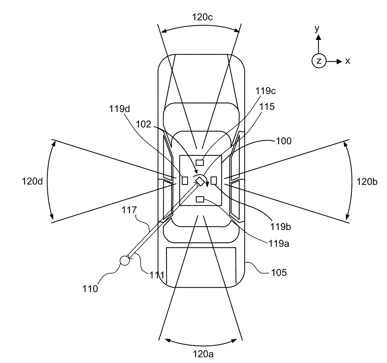
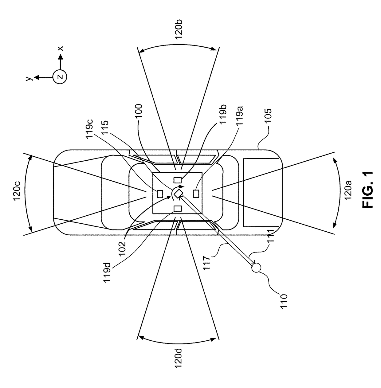
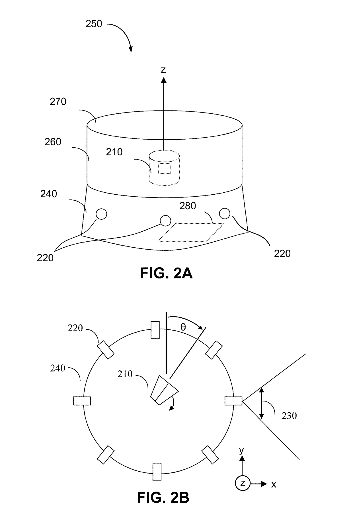
[0020]According to certain embodiments, methods and systems disclosed herein relate augmenting 360 degree panoramic LIDAR results with color. Embodiments of a 360 degree panoramic-view, color, spinning, LIDAR system (PCLS) augments its distance and intensity LIDAR results with color-camera information. The cameras and LIDAR system (e.g., emitters and sensors) can be constructed as a mechanically integrated unit that can be calibrated at factory during manufacture.

[0021]Part of the calibration can include the determination of a color-pixel-lookup table to determine the correspondence between LIDAR pixels (depth / ranging pixels) and color pixels, which may be done at different viewing object distances. A LIDAR pixel can comprise any information related to LIDAR sensing, e.g., a depth value, a signal strength value, a signal to noise ratio value, and the like. The color-pixel lookup table can specify which color image pixel(s) correspond to each LIDAR pixel for a given ranging measureme...


PUM


Abstract

Methods and systems can augment 360 degree panoramic LIDAR results (e.g., from a spinning LIDAR system) with color obtained from color cameras. A color-pixel-lookup table can specify the correspondence between LIDAR pixels (depth / ranging pixels) and color pixels, which may be done at different viewing object distances. The operation of the color cameras can be triggered by the angular positions of the LIDAR system. For example, a color image of a particular camera can be captured when the LIDAR system is at a particular angular position, which can be predetermined based on properties of the cameras (e.g., shutter speed). Alternatively or in addition, a common internal clock can be used to assign timestamps to LIDAR and color pixels as they are captured. The corresponding color pixel(s), e.g., as determined using a color-pixel-lookup table, with the closest timestamp can be used for colorization.

Description

CROSS-REFERENCES TO RELATED APPLICATIONS[0001]This application claims priority to U.S. Provisional Patent Application No. 62 / 506,460, filed May 15, 2017, entitled “Systems and Method for Augmenting 360° Panoramic LIDAR results with Color,” the entire contents of which are hereby incorporated by reference in their entireties for all purposes.BACKGROUND[0002]360 degree panoramic-view LIDAR systems can create a 3-dimensional map of a volume surrounding the system and therefore can be used in many applications such as vehicle safety and autonomous vehicle control. Most LIDAR systems employ monochromatic laser pulses and can measure both the intensity and time delay of the reflected laser pulse. From the intensity and time delay, the LIDAR system can then compute a LIDAR image comprising an array of LIDAR pixels, each pixel including the range (distance from the LIDAR system) and reflectivity of a detected object in the field around the system. However, such a LIDAR system is inherently ...

Claims


Application Information

Patent Timeline
Patent Type & Authority Applications(United States)
IPC IPC(8): G01S17/93H04N5/235H04N5/232G01S17/89G06T7/50G01S17/86G01S17/931
CPCG01S17/936H04N5/2353H04N5/23238G01S17/89G06T7/50G01S17/42G01S7/4813G01S7/497G01S7/51G01S17/931G01S17/86H04N23/80H04N23/698H04N23/73H04N23/10
Inventor PACALA, ANGUS
Owner OUSTER INC
Why Eureka
Try Eureka