Machine tool

a technology of machine tools and axes, which is applied in the direction of instrumentation, electric programme control, program control, etc., can solve the problems of positioning errors of items to be machined, and achieve the effect of minimizing the sum of the two screw axis lengths and minimizing the positioning error of items

Inactive Publication Date: 2018-11-15
FANUC LTD
View PDF9 Cites 1 Cited by
  • Summary
  • Abstract
  • Description
  • Claims
  • Application Information

AI Technical Summary

Benefits of technology

[0008](2) Preferably, in the machine tool of (1), the two axis member rotating devices and the two ball screws are provided, the longitudinal direction of one of the screw axis members has a position relationship parallel to the first direction, and the longitudinal direction of the other of the screw axis members has a position relationship parallel to the second direction and the control device performs control on the axis member rotating device and the stage rotating device such that when the part of the placement region in the stage is arranged in the position opposite the spindle cutter in the third direction, the sum of the two screw axis lengths is minimized and that the part of the placement region in the stage is moved to the position opposite the spindle cutter in the third direction.
[0009]According to the present invention, it is possible to provide a machine tool which can minimize an error in the positioning of an item to be machined without use of a thermal sensor or the like.

Problems solved by technology

Consequently, an error occurs in the positioning of the item to be machined.

Method used


Image

  • Machine tool
  • Machine tool
  • Machine tool

Examples


Embodiment Construction

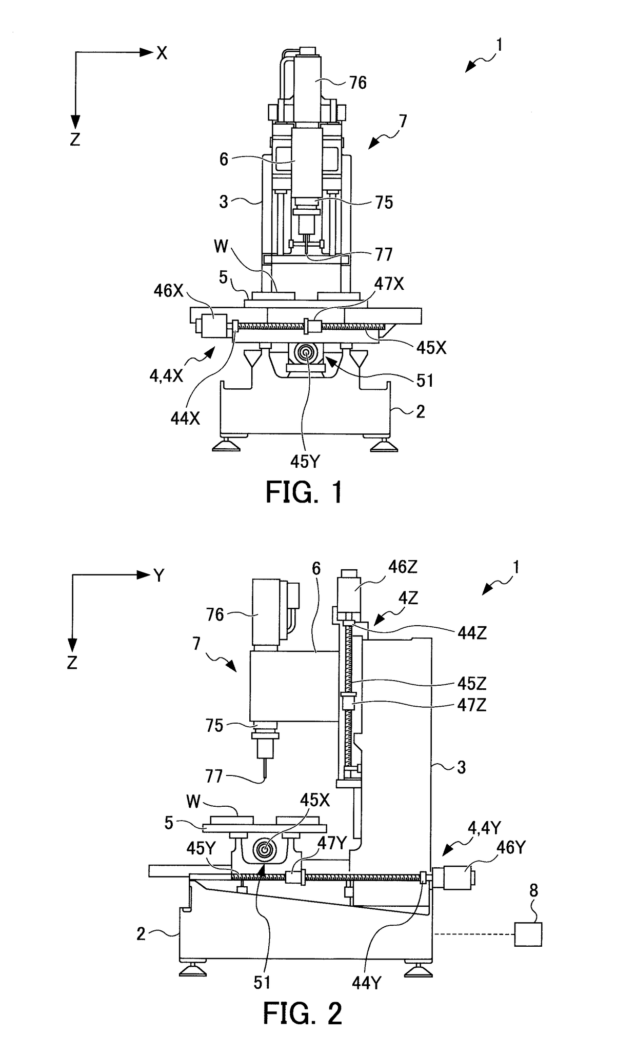
[0021]An embodiment of the present invention will be described below. FIG. 1 is a front view showing a machining center 1 according to the embodiment of the present invention. FIG. 2 is a side view showing the machining center 1 according to the embodiment of the present invention. A machine tool according to the present embodiment is formed with the machining center 1.

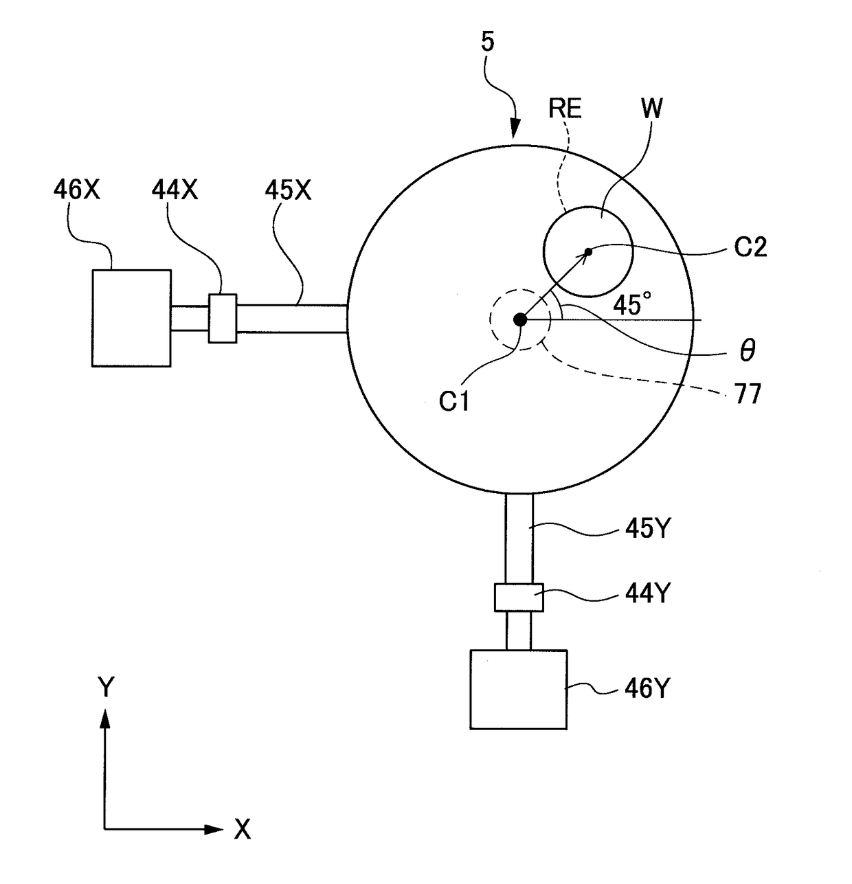
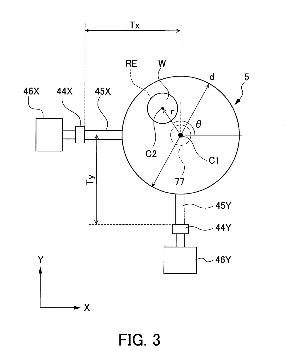
[0022]As shown in FIGS. 1 and 2, the machining center 1 includes a bed 2 and a column 3 which serve as a tool machine main body, feed axes 4, a work table 5 which serves as a stage, a spindle mounting base 6, a spindle portion 7 and a control device 8.

[0023]The feed axes 4 include: a feed axis 4X which is extended so as to have a position relationship parallel to an X axis direction (left / right direction in FIG. 1) that is a first direction; a feed axis 4Y which is extended so as to have a position relationship parallel to a Y axis direction (left / right direction in FIG. 2) that is a second direction; and a feed axis ...


PUM


Abstract

In a machine tool, a control device performs control on an axis member rotating device and a stage rotating device such that when part of a placement region RE in a stage is arranged in a position opposite a spindle cutter in a third direction, in a direction which is at least one of a first direction and a second direction and in which accuracy is required, a screw axis length from a connection portion of the screw axis member of a ball screw and an axis member rotating device to a nut portion is minimized and that the part of the placement region RE in the stage is moved to the position opposite the spindle cutter in the third direction.

Description

[0001]This application is based on and claims the benefit of priority from Japanese Patent Application No. 2017-094609, filed on 11 May 2017, the content of which is incorporated herein by reference.BACKGROUND OF THE INVENTIONField of the Invention[0002]The present invention relates to machine tools such as a machining center.Related Art[0003]Conventionally, a machine tool is known in which an item to be machined is placed on a stage (work table), the work table is rotated or moved in an X axis direction and a Y axis direction such that the item to be machined is moved to a position opposite a spindle cutter and thus the item to be machined is machined (for example, see Patent Document 1).[0004]Patent Document 1: Japanese Unexamined Patent Application, Publication No. S59-200305SUMMARY OF THE INVENTION[0005]In the machine tool disclosed in Patent Document 1, the work table is moved for example by a ball screw or the like, and in the ball screw, a temperature increase or a thermal di...

Claims


Application Information

Patent Timeline
Patent Type & Authority Applications(United States)
IPC IPC(8): G05B19/18B23Q3/155
CPCG05B19/182B23Q3/15503G05B2219/35354G05B2219/36503B23Q1/25B23Q5/40G05B19/042B23Q5/42
Inventor ZHI, CHAO
Owner FANUC LTD
Why Eureka
Try Eureka