Concentrated winding stator coil for an electric rotary machine

a stator coil and electric rotary machine technology, which is applied in the direction of transformers/inductance coils/windings/connections, transformers/inductance details, etc., can solve the problems of complex installation work for the rotor, wire contact with the rotor or the rotor, etc., to reduce the difference, suppress the increase in size and length of the electric rotary machine, and minimize the axial length of the stator

Inactive Publication Date: 2005-10-27
DENSO CORP
View PDF5 Cites 14 Cited by
  • Summary
  • Abstract
  • Description
  • Claims
  • Application Information

AI Technical Summary

Benefits of technology

[0023] According to a preferred embodiment of the present invention, the terminal bus bars of the first bus bar groups of respective phases are connected to the terminal bus bars of the second bus bar groups of corresponding phases at positions adjacent to an outer cylindrical surface of the stator core. This arrangement is effective in reducing the difference between the electric resistance of the serial coil units belonging to the first bus bar group and the electric resistance of the serial coil units belonging to the second bus bar group.
[0024] According to a preferred embodiment of the present invention, the terminal bus bars of either the first bus bar group or the second bus bar group extend in slots of the stator core and are connected to the terminal bus bars of the other of the first and second bus bar groups. This arrangement brings the effect of suppressing increase in size and length of the electric rotary machine because the inside space of the stator core can be effectively utilized for the bus bars (usually, the terminal bus bars) connecting the first bus bar group and the second bus bar group.
[0025] According to a preferred embodiment of the present invention, respective bus bars belonging to the first bus bar groups and the second bus bar groups are disposed so as to offset toward the stator core from the teeth in the axial direction than the surface of the tooth coils. According to this arrangement, respective bus bars do not protrude than the tooth coils in the axial direction. Thus, the axial length of the stator can be minimized.
[0026] According to a preferred embodiment of the present invention, each of the tooth coils has a turn number which can be regarded as being equivalent to an odd turn number if all of the tooth coils arranging the phase winding are connected in series. According to this arrangement, it becomes possible to provide a tooth coil having substantially an odd turn number while assuring the advantages of the proximal end extraction type two-layer winding arrangement. The degree of freedom in designing an electric rotary machine using a concentrated winding stator can be increased.
[0027] More specifically, it is now supposed that “i” represents the current flowing in the phase winding, “N” represents a turn number of the tooth coil, and the phase winding is arranged by serially connecting a total of “Y” tooth coils in parallel with each other. According to this arrangement, the phase current flowing in each tooth coil decreases to 1 / Y level. This is equivalent to the reduction in the ampere-turn of one tooth coil from Ni to Ni / Y. In other words, this is equivalent to the reduction in the turn number of the tooth coil from N to N / Y. Accordingly, even if an actual turn number of the tooth coil is an even number, it is possible to realize a turn number that can be regarded as an odd number electromagnetically. For example, it is further supposed that the tooth coil has 30 turns and the phase windings, each consisting of 6 tooth coils, are connected in parallel with each other. According to this arrangement, the turn number of the tooth coil can be regarded as being substantially identical with 5 turns. Furthermore, according to the preferred embodiment of the present invention, the phase winding is arranged by connecting two serial coil units in parallel with each other. This arrangement brings the effect of suppressing reduction in the current flowing in each tooth coil because the number of parallel units is 2 (i.e. the minimum number). Accordingly, it becomes possible to reduce the turn number of a tooth coil required for assuring an ampere-turn required for one tooth coil. The winding work of the tooth coil can be simplified. The coil resistance can be reduced.

Problems solved by technology

However, the tooth coils disclosed in the prior art 1 are complicated to manufacture.
If these wires are loosened and subjected to vibrations, there will be the possibility that the wires contact with the rotor or installation work for the rotor will become complicated.

Method used


Image

  • Concentrated winding stator coil for an electric rotary machine
  • Concentrated winding stator coil for an electric rotary machine
  • Concentrated winding stator coil for an electric rotary machine

Examples


first embodiment

Overall Structure

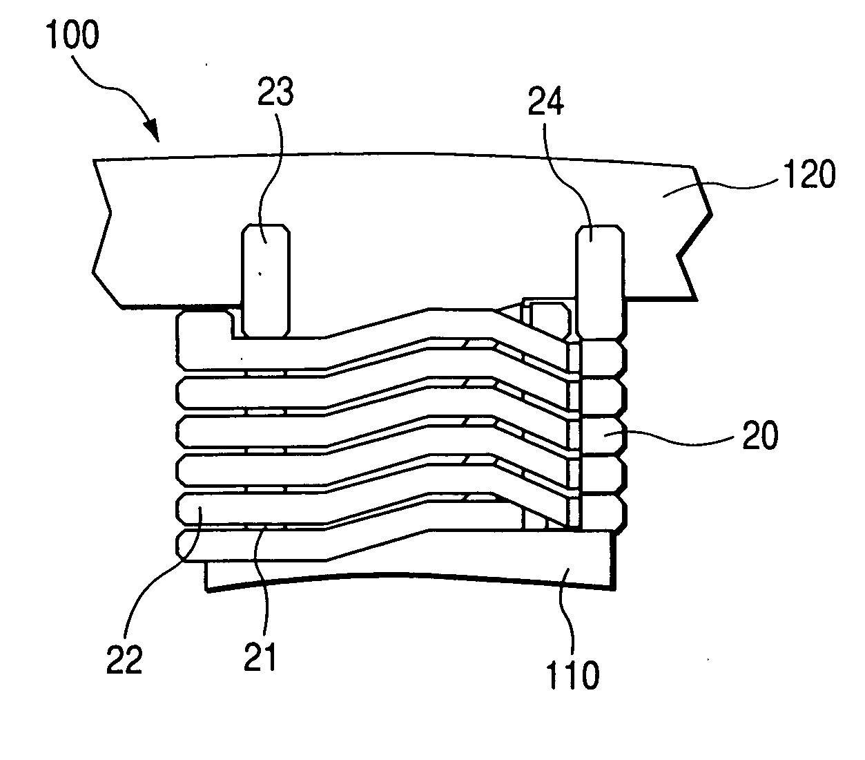
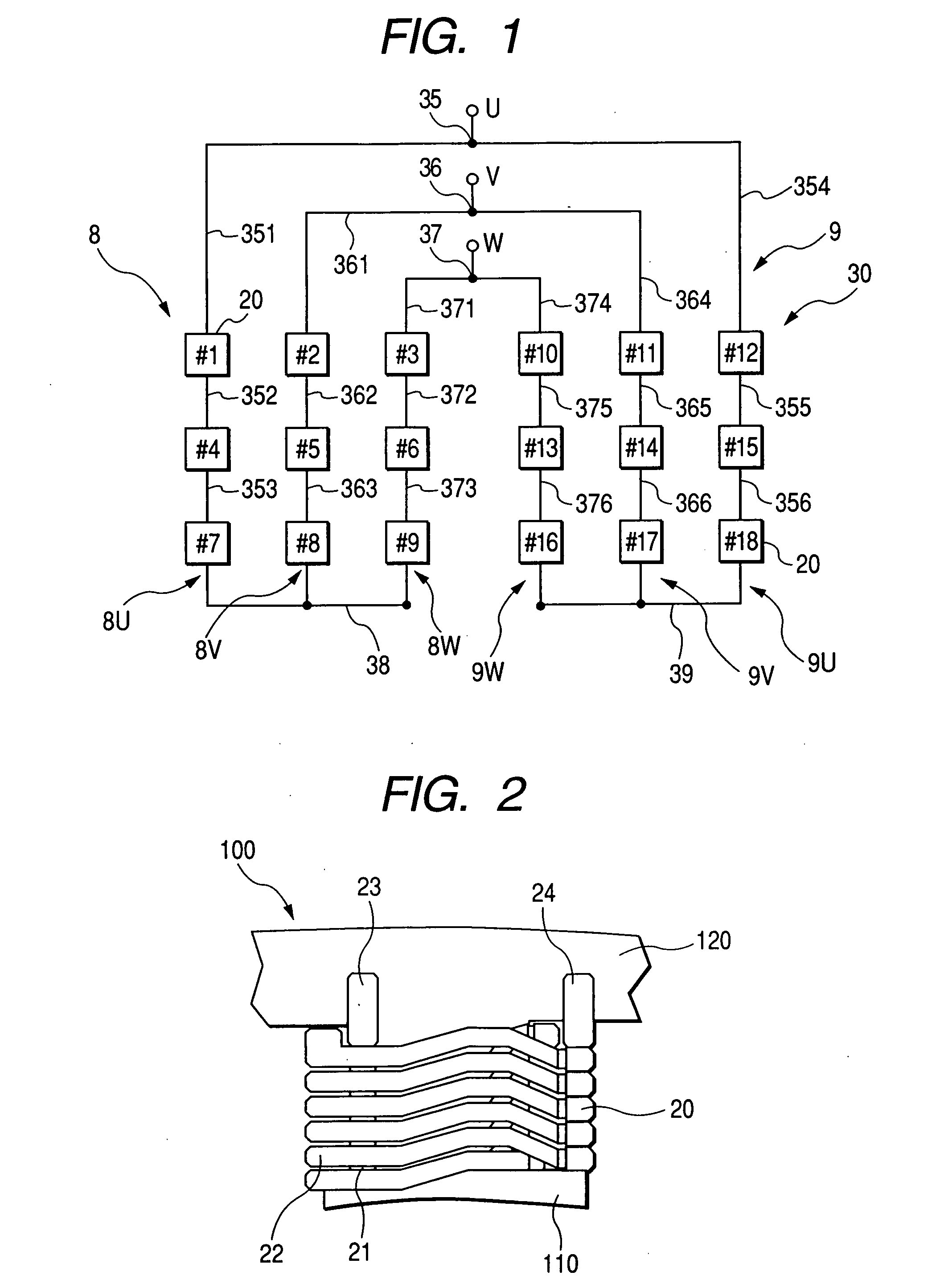
[0044] A concentrated winding stator having serial / parallel proximal end extraction type two-layer winding coils in accordance with a first embodiment of the present invention will be explained with reference to FIG. 1 showing a wiring arrangement and FIG. 2 partly showing a front view of the stator. A stator core 100 consists of a total of eighteen teeth 110 and a single core back 120. The stator core 100 is arranged by multilayered electromagnetic steel plates. The stator core 100 has an assembled core structure, although FIG. 2 does not show the details of the assembled core structure.

[0045] Each tooth 110 protrudes inward in the radial direction from an inner cylindrical surface of the core back (i.e. yoke) 120. The teeth 110 are disposed at constant angular pitches in the circumferential direction. Each tooth 110 has a partially cylindrical surface located at the radial inner side thereof so as to confront with a rotor (not shown). Tooth coils 20 are wound ar...

second embodiment

[0068] A winding stator coil in accordance with a second embodiment of the present invention will be explained with reference to FIG. 5 which schematically shows one tooth coil 20 fixed to the stator core. FIG. 5 shows an arrangement for the first-layer bus bar group 81, the second-layer bus bar group 82, the third-layer bus bar group 83, the fourth-layer bus bar group 91, the fifth-layer bus bar group 92, and the sixth-layer bus bar group 93 respectively shown in FIG. 4.

[0069] More specifically, the bus bar group 81 consists of the first-layer bus bars 352, 353, 38, 355, 356, and 39 shown in FIG. 4. The bus bar group 82 consists of the second-layer bus bars 362, 363, 365, and 366 shown in FIG. 4. The bus bar group 83 consists of the third-layer bus bars 372, 373, 375, and 376 shown in FIG. 4. Furthermore, the bus bar group 91 consists of the fourth-layer bus bars 351 and 354 shown in FIG. 4. The bus bar group 92 consists of the fifth-layer bus bars 361 and 364 shown in FIG. 4. The...

third embodiment

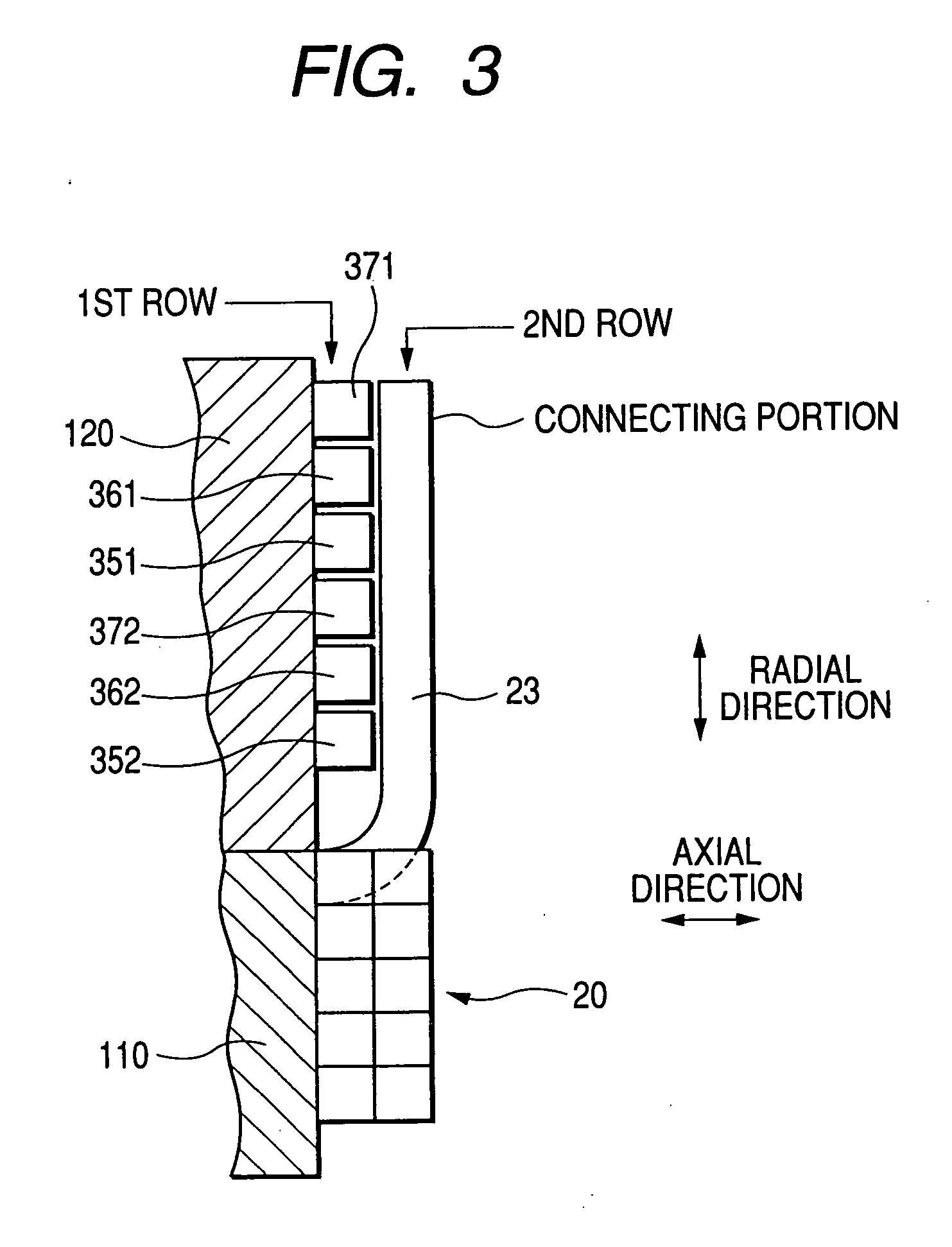
[0074] A winding stator coil in accordance with a third embodiment of the present invention will be explained with reference to FIG. 6 which schematically shows a modified arrangement of the bus bar groups 81-83 and 91-93. According to this embodiment, the bus bar groups 91 to 93 are disposed successively in the radial direction along the core back 120. The bus bar groups 81 to 83 are disposed successively in the radial direction and are positioned outside the bus bar group 91 to 93 in the axial direction. According to this arrangement, it is necessary to solve the problem of intersection of the radial extended portion of the bus bar being extended in the radial direction and connected to the lead wire of the tooth coil 20 and the circumferential extended portion of other bus bar being extended in the circumferential direction.

[0075] According to this and above-described embodiments, the external connecting terminals 35, 36, and 37 are disposed at appropriate positions so that the ...


PUM

PropertyMeasurementUnit
circumferential widthaaaaaaaaaa
axial lengthaaaaaaaaaa
lengthaaaaaaaaaa

Abstract

A concentrated winding stator coil of a proximal end extraction type two-layer winding arrangement includes numerous tooth coils which are connected in series to arrange serial coil units and also connected in parallel as pairs arranging respective phase windings. Plural inter-coil bus bars are provided to connect the tooth coils of the serial coil units. Plural terminal bus bars extend from both ends of the serial coil units to connect respective serial coil units in parallel with each other. These bus bars are disposed adjacently to an end face of a core back.

Description

CROSS-REFERENCE TO RELATED APPLICATION [0001] This application is based upon and claims the benefit of priority from earlier Japanese Patent Application No. 2004-130186 filed on Apr. 26, 2004 so that the description of which is incorporated herein by reference. BACKGROUND OF THE INVENTION [0002] This invention relates to a concentrated winding stator coil for an electric rotary machine. [0003] A concentrated winding stator, conventionally proposed in the field of electric rotary machines, includes a plurality of phase windings each consisting of same phase coils connected with each other and wound in a concentrated manner around respective teeth of a stator core (hereinafter, referred to as tooth coils). From requirements of the winding work, this kind of concentrated winding stator is generally used for an assembled core which is formed by assembling separated partial cores of respective teeth into a stator core. [0004] The tooth coils of a concentrated winding stator are wound aro...

Claims


Application Information

Patent Timeline
Patent Type & Authority Applications(United States)
IPC IPC(8): H02K3/00H02K3/04H02K3/18H02K3/28H02K3/46H02K3/52H02K15/095
CPCH02K2203/09H02K3/522
Inventor YONEDA, SHIGENORIYOSHINAGA, SOICHI
Owner DENSO CORP
Why Eureka
Try Eureka