
Turbine center frame having a specifically designed annular space contour

Active Publication Date: 2019-11-28
MTU AERO ENGINES GMBH
View PDF0 Cites 0 Cited by
  • Summary
  • Abstract
  • Description
  • Claims
  • Application Information

AI Technical Summary

Benefits of technology

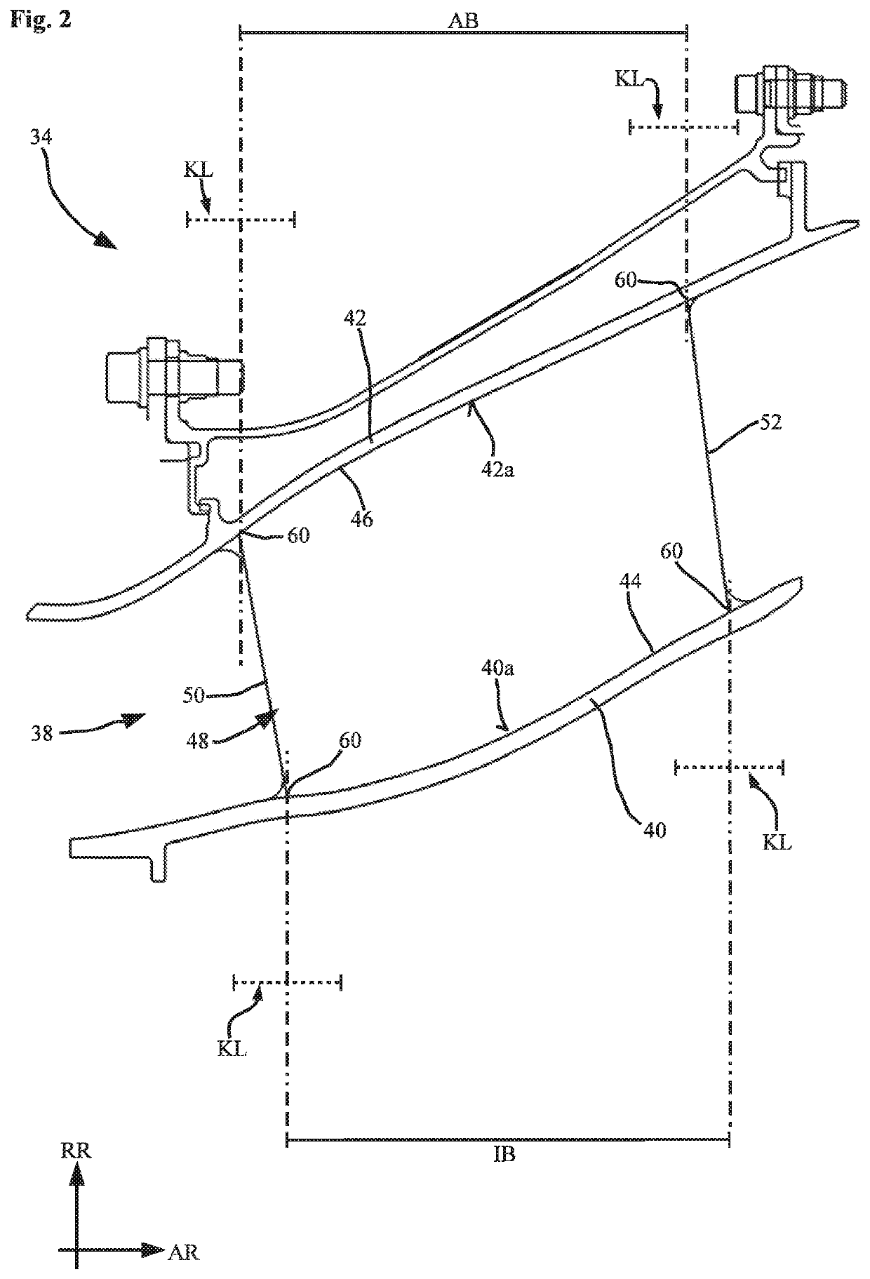
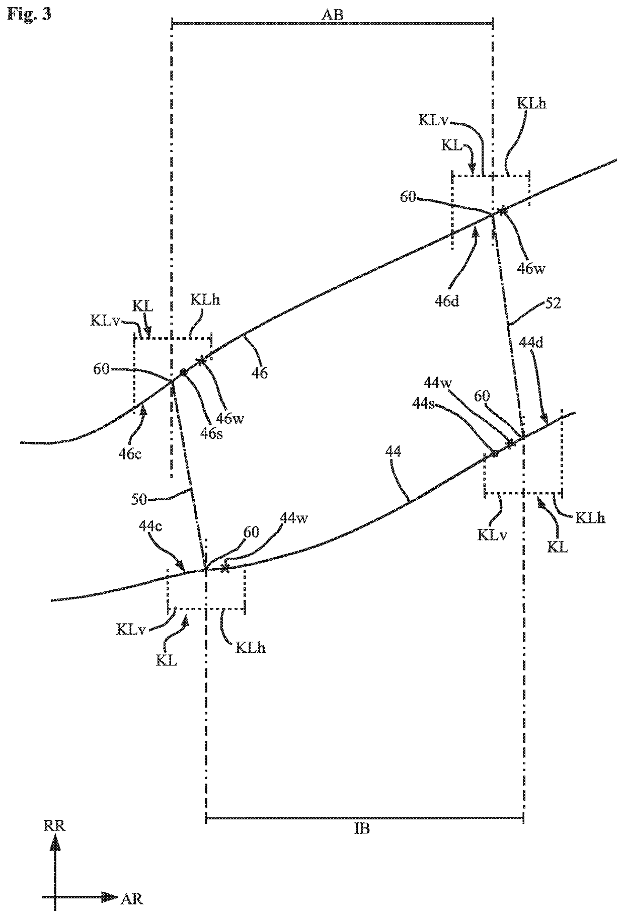
The present invention provides a turbine center frame that can be shorter in axial length while preventing flow separations from occurring along the walls of the annular space. This is achieved by providing inflection points and points of maximum slope in the leading and trailing edge regions, which optimizes the curved shape of the annular space and prevents the flow from separating. The inflection points and points of maximum slope are located in the region of the leading edge and trailing edge, respectively.

Problems solved by technology

This involves the risk of flow separations occurring in the region of the outer wall or inner wall.

Method used


Image

  • Turbine center frame having a specifically designed annular space contour
  • Turbine center frame having a specifically designed annular space contour
  • Turbine center frame having a specifically designed annular space contour

Examples


Embodiment Construction

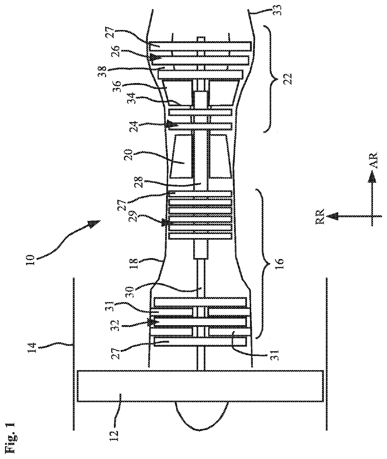
[0025]FIG. 1 shows, in simplified schematic form, an aircraft gas turbine 10, illustrated, merely by way of example, as a turbofan engine. Gas turbine 10 includes a fan 12 that is surrounded by a schematically indicated casing 14. Disposed downstream of fan 12 in axial direction AR of gas turbine 10 is a compressor 16 that is accommodated in a schematically indicated inner casing 18 and may include a single stage or multiple stages. Disposed downstream of compressor 16 is combustor 20. Hot exhaust gas discharging from the combustor then flows through subsequent turbine 22, which may be single-stage or multi-stage. In the present example, turbine 22 includes a high-pressure turbine 24 and a low-pressure turbine 26. A hollow shaft 28 connects high-pressure turbine 24 to compressor 16, in particular a high-pressure compressor 29, so that they are jointly driven or rotated. Another shaft 30 located further inward in the radial direction RR of the turbine connects low-pressure turbine 26...


PUM


Abstract

Described is a turbine center frame for a gas turbine, in particular an aircraft gas turbine, the turbine center frame having a radially inner wall and a radially outer wall bounding an annular space through which hot gas flows and each having a contour facing the annular space, the contours describing an inner annular space curve along the inner wall and an outer annular space curve along the outer wall. At least one vane element extends in the radial direction through the annular space and has an axial leading edge and an axial trailing edge, the vane element having an outer axial width. The outer annular space curve or / and the inner annular space curve have at least one curve section having an inflection point of the respective annular space curve or / and a point of maximum slope of the respective annular space curve, the curve section being located in the region of the leading edge or trailing edge as considered with respect to the outer axial width or / and the inner axial width and having a length projected parallel to the axial direction which length is up to 20% of the respective axial width, and the curve section intersecting the piercing point where the leading edge or the trailing edge pierces the outer wall or the inner wall.

Description

[0001]This claims the benefit of German Patent Application DE 102018208151.4, filed May 24, 2018 which is hereby incorporated by reference herein.[0002]The present invention relates to a turbine center frame for a gas turbine, in particular an aircraft gas turbine, the turbine center frame having a radially inner wall and a radially outer wall, the inner wall and the outer wall bounding an annular space through which hot gas flows, the inner wall and the outer wall each having a contour facing the annular space, the contours describing an inner annular space curve along the inner wall and an outer annular space curve along the outer wall when viewed in an axial longitudinal section through the turbine center frame, the turbine center frame further having at least one vane element extending in the radial direction through the annular space and having an axial leading edge and an axial trailing edge, the vane element having an outer axial width, taken with respect to the outer wall an...

Claims


Application Information

Patent Timeline
IPC IPC(8): F01D9/04
CPCF05D2240/12F05D2220/323F01D9/042F01D5/143F01D9/041F05D2250/713Y02T50/60
Inventor BRETTSCHNEIDER, MARKUSLAUER, CHRISTOPHSTANKA, RUDOLF
Owner MTU AERO ENGINES GMBH
Learn More