
Ignition coil

a technology of ignition coil and coil body, which is applied in the direction of coils, transformers/inductance details, and inductances, etc., can solve the problems of insufficient magnitude of high current pulse, undetected effects of secondary winding, and inability to factor in high current pulse into secondary winding design, etc., to minimize the axial length of secondary winding and minimize the packaging size of ignition coil.

Active Publication Date: 2015-12-17
DELPHI TECH IP LTD
View PDF2 Cites 5 Cited by
  • Summary
  • Abstract
  • Description
  • Claims
  • Application Information

AI Technical Summary

Benefits of technology

The patent text describes an ignition coil that generates a spark to ignite a fuel in an engine. The coil has a unique design with two sections of wire wound around a magnetic core. The first section is thicker than the second section to maintain a safe voltage level but minimize the size of the coil. This design helps to reduce the space needed for the coil and ensures a consistent and reliable spark.

Problems solved by technology

Unless the high current pulse is properly dealt with, the secondary winding may be undesirably affected by the high current pulse.
The high current pulse is most easily limited by using a high resistance spark plug.
High resistance spark plugs were common in less-recent internal combustion engines, and consequently, the high current pulse was not of sufficient magnitude to need to be factored into the secondary winding design.
However, more modern internal combustion engines are commonly utilizing lower resistance spark plugs in order to boost energy from the coil, thereby resulting in higher voltages and making the high current pulse a magnitude that may not be compatible with the secondary winding.
However, since the progressive winding strategy is wound uninterrupted around the secondary winding spool, the potential difference between the outermost winding and the innermost winding is greater than in the segmented winding strategy.
In order to minimize the potential difference between the outermost winding and the innermost winding in the progressive winding, the secondary winding may be increased in axial length, thereby decreasing the thickness of the secondary winding by spreading the number of windings over a greater length, however, this may not be possible to do while maintaining a desired packaging size of the ignition coil.

Method used


Image

  • Ignition coil
  • Ignition coil
  • Ignition coil

Examples


Embodiment Construction

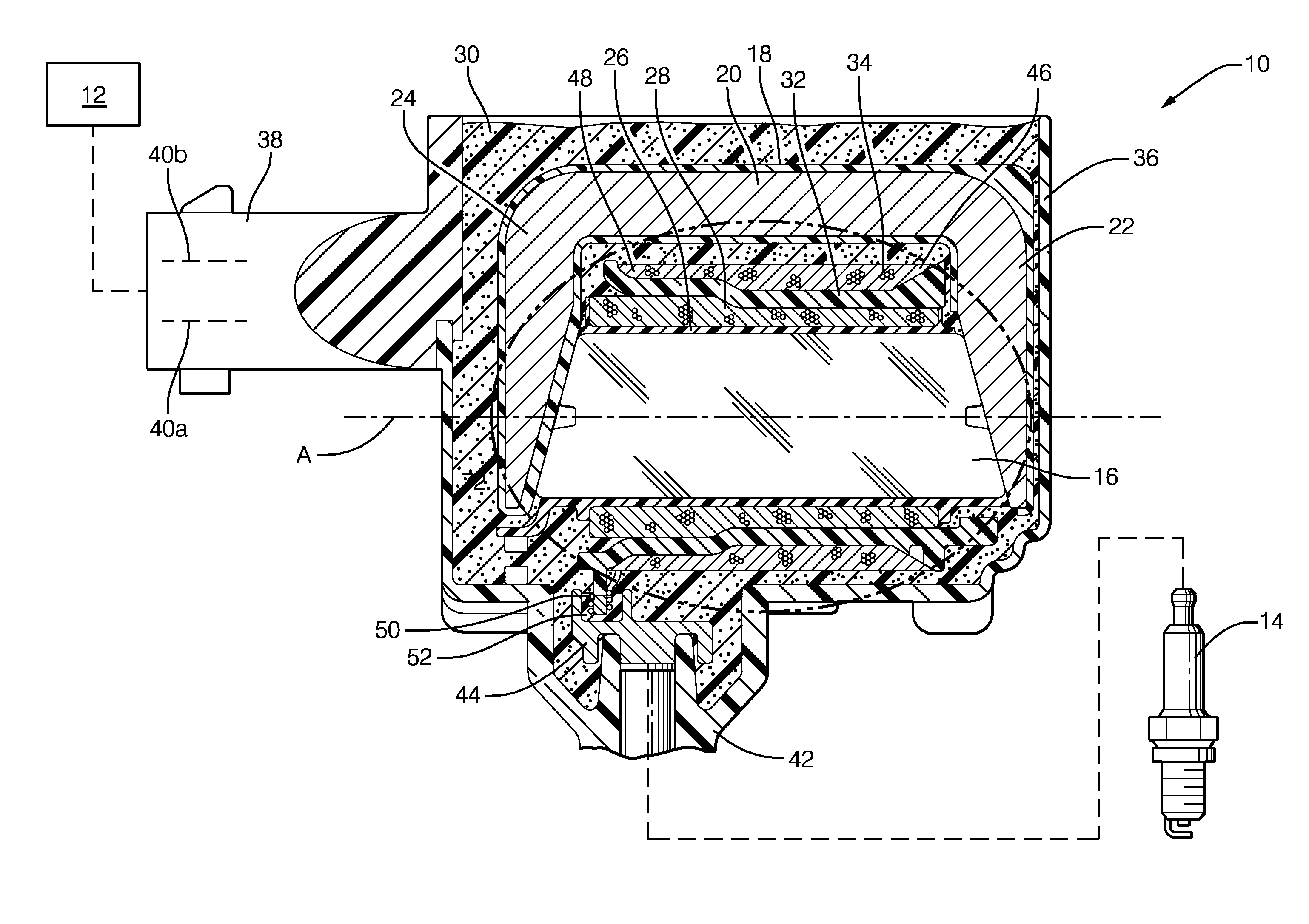
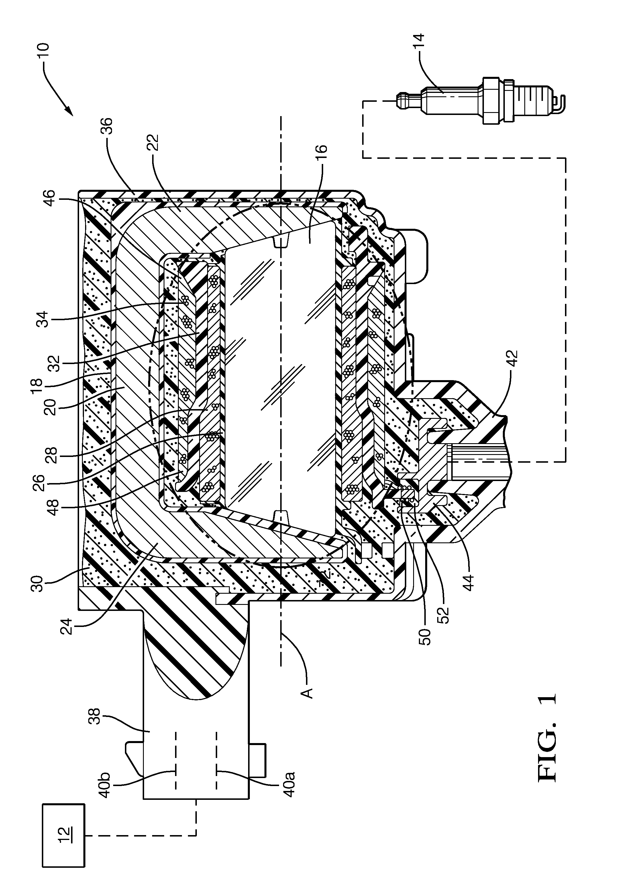
[0013]Reference will first be made to FIG. 1 which shows a simplified cross-sectional view of an ignition coil 10. Ignition coil 10 may be controlled by a control unit 12 or the like. Ignition coil 10 is configured for connection to a spark plug 14 that is in threaded engagement with a spark plug opening (not shown) in an internal combustion engine (also not shown). Ignition coil 10 is configured to deliver a high-voltage spark-generating current to spark plug 14, as shown. Generally, overall spark timing (dwell control) and the like is provided by control unit 12. One ignition coil 10 may be provided per spark plug 14.

[0014]Ignition coil 10 may include a magnetically-permeable core 16, a magnetically-permeable structure 18, hereinafter referred to as high-permeance structure 18, configured to provide a high permeance magnetic return path which has a base section 20 and a pair of legs 22 and 24, a primary winding spool 26, a primary winding 28, a quantity of encapsulant 30 such as a...


PUM

PropertyMeasurementUnit
spark-generating currentaaaaaaaaaa
voltageaaaaaaaaaa
thicknessaaaaaaaaaa

Abstract

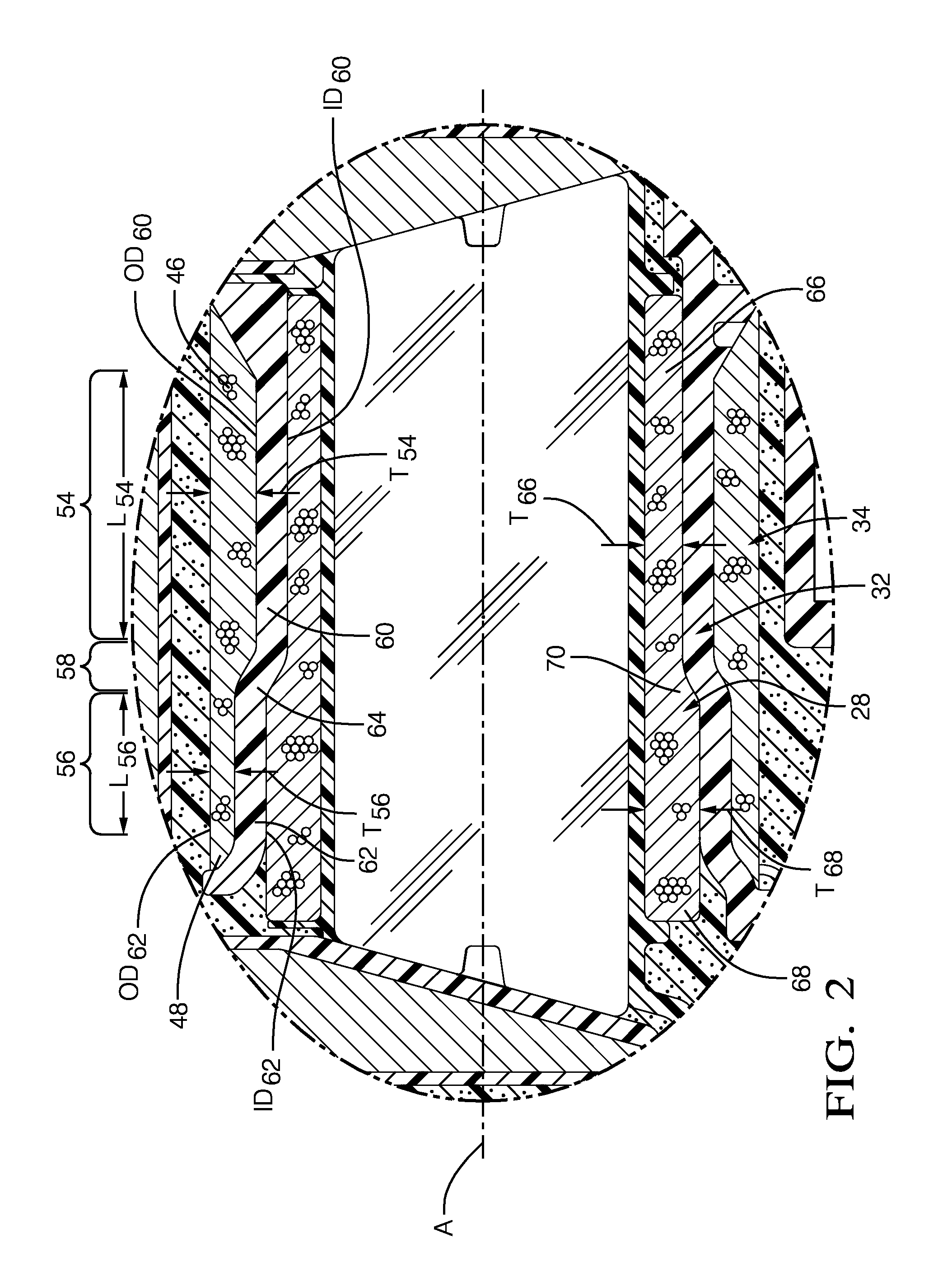
An ignition coil for delivering a spark-generating current to a spark plug includes a magnetically-permeable core; a primary winding disposed outward of the core; and a secondary winding radially surrounding the primary winding and inductively coupled to the primary winding, the secondary winding having a low-voltage end and a high-voltage end. The secondary winding includes a secondary winding first section proximal to the low-voltage end and having a first thickness. The secondary winding also includes a secondary winding second section proximal to the high-voltage end and having a second thickness that is less than the first thickness of the secondary winding first section.

Description

CROSS-REFERENCE TO RELATED PATENT APPLICATIONS[0001]This patent application claims the benefit of U.S. provisional patent application Ser. No. 62 / 012,557 filed on Jun. 16, 2014, the disclosure of which is hereby incorporated by reference in its entirety.TECHNICAL FIELD OF INVENTION[0002]The present invention relates to an ignition coil for developing a spark-generating current that is applied to a spark plug and more particularly to such an ignition coil with a secondary winding which maintains an acceptable wire to wire voltage when subjected to a current pulse.BACKGROUND OF INVENTION[0003]Ignition coils are known for use in connection with an internal combustion engine such as an automobile engine. Ignition coils typically include a core around which is wound a primary winding. A secondary winding is wound around a secondary winding spool to surround the primary winding such that a high voltage is induced on the secondary winding when an electric current applied to the primary win...

Claims


Application Information

Patent Timeline
Patent Type & Authority Applications(United States)
IPC IPC(8): H01F27/28H01F27/32
CPCH01F27/325H01F27/2823H01F38/12H01F2005/025H01F27/29
Inventor SKINNER, ALBERT A.HAMER, COLINLEVERS, JR., HARRY O.
Owner DELPHI TECH IP LTD
Learn More