
Loudspeakers

a loudspeaker and axial length technology, applied in the field of loudspeakers, can solve the problems of complex manufacturing of such an arrangement, reducing the effectiveness of the absorber, and much more difficult design and manufacture of the metamaterial, so as to minimise the axial length of the loudspeaker and dissipate acoustic energy.

Active Publication Date: 2021-06-24
GP ACOUSTICS INT
View PDF4 Cites 0 Cited by
  • Summary
  • Abstract
  • Description
  • Claims
  • Application Information

AI Technical Summary

Benefits of technology

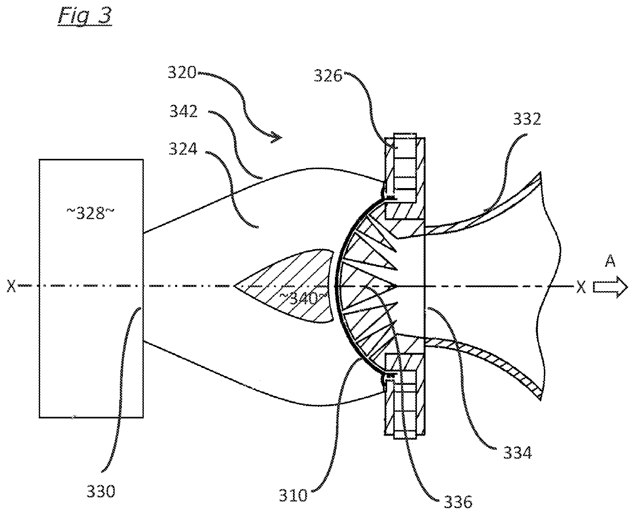
The patent describes a design for a loudspeaker that allows the rear sound to be effectively channelled to the metamaterial absorber, which can be located further away from the diaphragm. This design allows for more freedom over the metamaterial design and mechanical construction. However, there can be a problem of reflections from the metamaterial at the interface between the duct and the metamaterial absorber. To address this issue, the patent suggests aligning the channels with a surface normal or at an angle to the duct aperture to minimize reflections. The front surface of the metamaterial absorber is located at the opening at the rearward end of the duct, which allows the metamaterial to spread out from the central axis of the loudspeaker. The cross-sectional area of the duct can taper or decrease linearly in a rearward direction to the opening at its rearward end. This design effectively moves the metamaterial absorber away from the rear of the diaphragm, making more space available for other loudspeaker elements.

Problems solved by technology

The manufacture of such an arrangement is complicated.
In addition, the structural walls that form the channels through the metamaterial occupy volume and, in some arrangements, this can reduce the effectiveness of the absorber.
This makes the design and manufacture of the metamaterial much more challenging due to practical limitations on minimum metamaterial wall thickness.
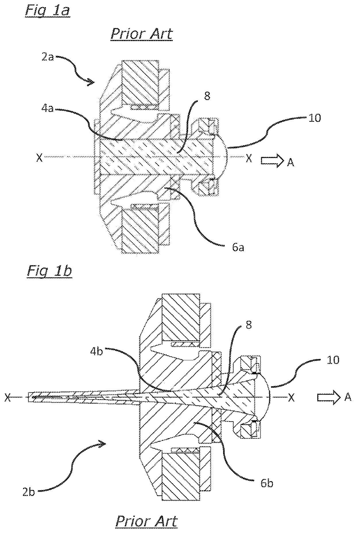
In particular, since the structural walls of the metamaterial occupy volume and thus a proportion of the cross-sectional area of the duct 4a, 4b, this severely limits the effective open area that the metamaterial presents to the rear radiated sound, and consequently the path of the rear sound wave is significantly impeded.
This issue is particularly severe if, in order to increase the viscous losses, extremely narrow metamaterial channels are used—because more channels require more walls, which take up a greater proportion of the cross-sectional area of the rearward-leading duct.
Although the metamaterial absorber can be designed to have extremely low reflection, this arrangement makes the effect of even a small reflection by the metamaterial much more problematic.
This effect introduces irregularities into the driver diaphragm movement due to the reflective wave impinging on the diaphragm, and these irregularities can be severe even if the reflection from the metamaterial is a small percentage of the incident sound arriving at the metamaterial.
A significant proportion of the absorbent surface is formed by the walls separating adjacent channels, but these walls decrease the ‘opening area’ of the channels making it smaller than the ‘opening area’ of the driver duct* resulting in reflections.

Method used


Image

  • Loudspeakers
  • Loudspeakers
  • Loudspeakers

Examples


Embodiment Construction

[0022]FIG. 1a shows a high-frequency driver with a 25.4 mm diameter diaphragm using a large central vent tube / duct filled with dense acoustical wadding. FIG. 1b shows a high-frequency driver with a 25.4 mm diameter diaphragm using a 120 mm long, exponentially tapering duct which is also filled with dense acoustical wadding.

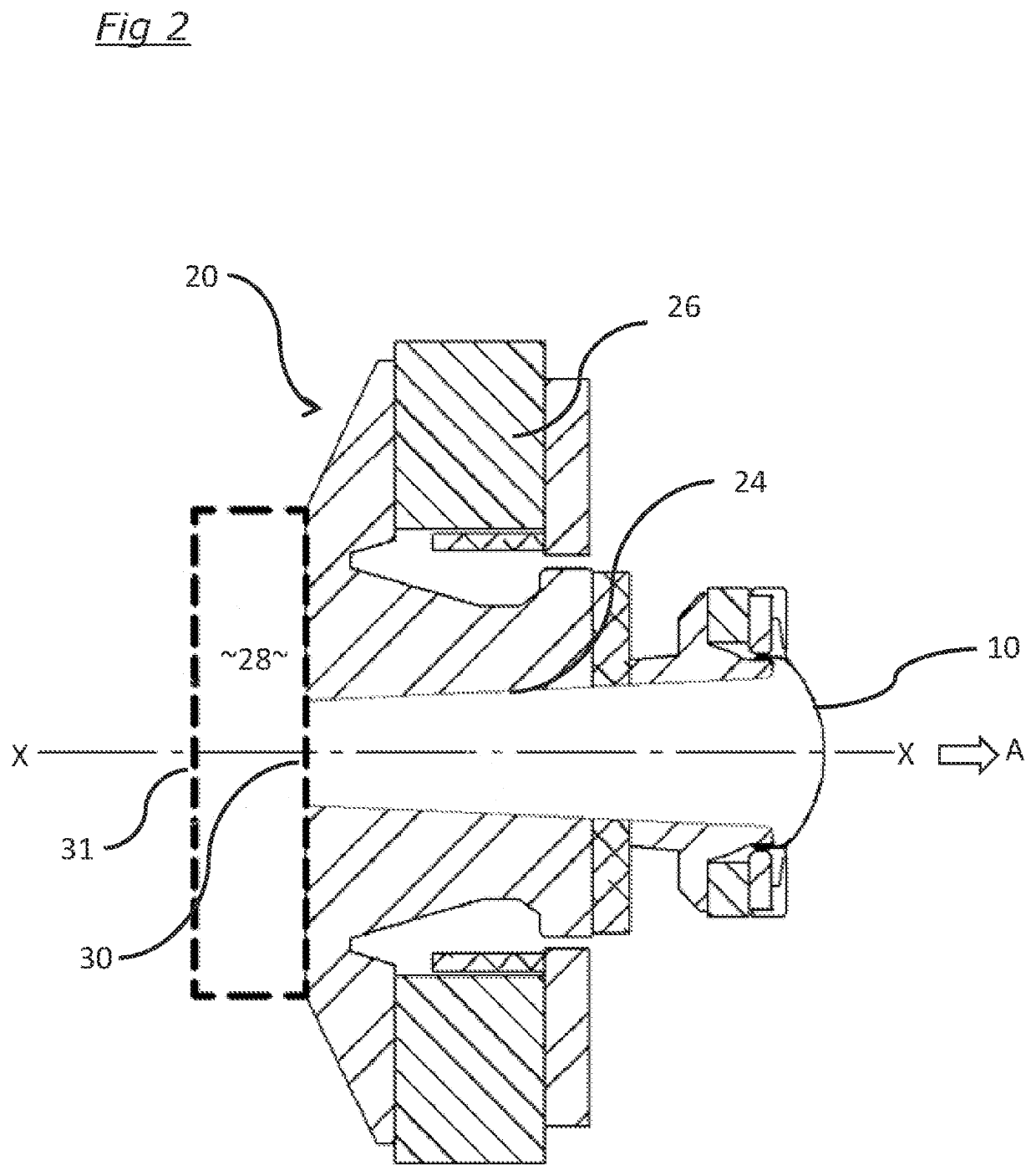
[0023]FIG. 2 shows in cross-section a tweeter 20 forming part of a coaxial driver with a highly effective arrangement according to this invention. The conical duct 24 through the drive unit 26 connecting the 25.4 mm diameter diaphragm 10 to the front surface 30 of the acoustic metamaterial 28 results in a spherical contracting acoustical wave with radius 146.4 mm at the front surface 30 of the metamaterial 28. The characteristic acoustical impedance of this wave is a close match to the impedance of the metamaterial described in WO 2018 / 047153 when a design frequency of 600 Hz is used. The impedance match in this case is not perfect and only over a limited bandwidt...


PUM


Abstract

A loudspeaker comprising: an acoustic diaphragm having front and rear surfaces, the acoustic diaphragm in use being driven so as to vibrate and radiate acoustic waves from its front surface in a forward direction away from the loudspeaker and from its rear surface in a rearward direction, and a drive unit located rearwardly or to the front / outside of the diaphragm, there being at least one open duct leading in a rearward direction away from the diaphragm, in which the at least one open duct has a cross-sectional area which decreases in the rearward direction, and in which acoustic waves radiated from the rear surface of the diaphragm pass through the open duct before contacting a front surface of an acoustic metamaterial absorber located generally behind the drive unit and immediately to the rear of the duct.

Description

CROSS REFERENCE TO RELATED APPLICATION[0001]This application claims priority to and benefits of GB Patent Application No. 1919144.4, filed Dec. 23, 2019 and GB Patent Application No. 2017429.8, filed Nov. 4, 2020, the content of which are hereby incorporated by reference in their entirety.FIELD OF THE INVENTION[0002]The present invention relates to loudspeakers.BACKGROUND ART[0003]The structure and operation of moving coil loudspeaker drive units is well known. A vibration diaphragm is attached to a coil of wire known as a voice coil, and the voice coil is placed in a magnetic field usually provided by one or more permanent magnets (together the voice coil and magnets being termed a motor or drive unit). When an alternating current is passed through the voice coil a force is induced in the voice coil, causing it to reciprocate and the diaphragm to vibrate and so to radiate acoustic waves. Acoustic waves are radiated from both sides of the diaphragm; the sound radiated from the front...

Claims


Application Information

Patent Timeline
Patent Type & Authority Applications(United States)
IPC IPC(8): H04R1/28H04R31/00
CPCH04R1/288H04R31/00H04R9/06G10K11/22G10K11/002G10K11/025H04R1/2865H04R1/36H04R9/025H04R2201/34H04R2400/13G10K11/162H04R1/28H04R1/2803H04R1/2861
Inventor OCLEE-BROWN, JACK ANTHONYDEGRAEVE, SEBASTIEN
Owner GP ACOUSTICS INT
Learn More