Support assembly for a propeller shaft

a technology of supporting assembly and propeller shaft, which is applied in the direction of engine components, turbine/propulsion lubrication, jet propulsion plants, etc., can solve the problems of overshadowing the gain associated with an increase in bearing span and the increase in engine overall length

Active Publication Date: 2018-11-22
PRATT & WHITNEY CANADA CORP
View PDF1 Cites 15 Cited by
  • Summary
  • Abstract
  • Description
  • Claims
  • Application Information

AI Technical Summary

Problems solved by technology

However, increasing the bearing span usually results in an increase of an overall length of the gas turbine engine.
Therefore, the gain ass

Method used


Image

  • Support assembly for a propeller shaft
  • Support assembly for a propeller shaft
  • Support assembly for a propeller shaft

Examples


Embodiment Construction

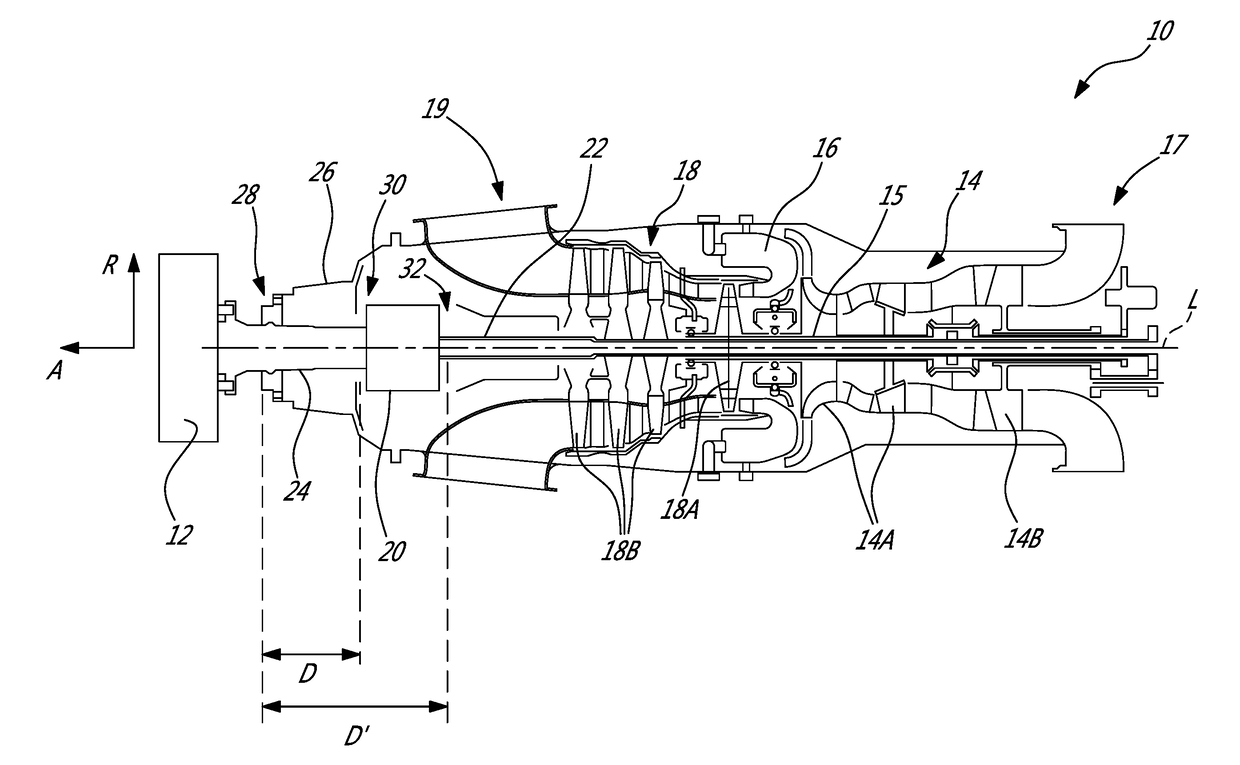
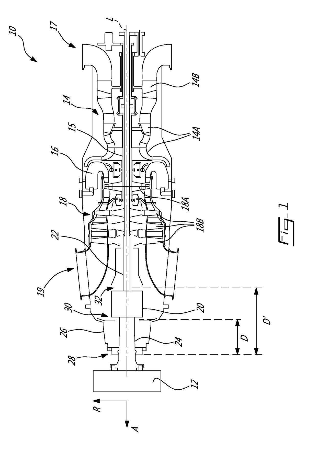
[0014]FIG. 1 illustrates a gas turbine engine 10 of a type preferably provided for use in subsonic flight and configured for driving a rotating component 12, such as, but not limited to, a propeller or a helicopter rotor. Depending on the intended use, the engine 10 may be any suitable aircraft engine, and may be configured as a turbo propeller engine or a turboshaft engine. The gas turbine engine 10 generally comprises in serial flow communication a compressor section 14 for pressurizing the air, a combustor 16 in which the compressed air is mixed with fuel and ignited for generating an annular stream of hot combustion gases, and a turbine section 18 for extracting energy from the combustion gases.

[0015]The exemplary embodiment shown in FIG. 1 is a “reverse-flow” engine because gases flow from the inlet 17, at a rear portion of the engine 10, to the exhaust outlet 19, at a front portion of the engine 10. This is in contrast to “through-flow” gas turbine engines in which gases flow ...


PUM


Abstract

A turbo propeller engine comprises a housing circumferentially extending around a longitudinal axis and disposed around a gearbox. The turbo propeller engine includes a propeller outside of the housing and a shaft surrounded in part by the housing and extending along the longitudinal axis. The shaft has a front end and a rear end. The propeller is mounted to the front end. The rear end is in a driven engagement with an output of the gearbox. The shaft is rotatably supported by a first bearing and by a second bearing separated from the first bearing by an axial distance along the longitudinal axis. The first and second bearings are disposed on opposite sides of the gearbox. The first bearing is disposed between the shaft and the housing, the second bearing is disposed between the housing and a component of the gearbox to rotatingly support the component of the gearbox.

Description

TECHNICAL FIELD[0001]The application generally relates to turbo propeller engines, and, more particularly, to a support assembly to support a propeller shaft of such engines, and related method.BACKGROUND OF THE ART[0002]A propeller of a turbo propeller gas turbine engine is mounted on a shaft supported by bearings to allow rotation of the shaft relative to its longitudinal axis and to transfer the torque from the engine to the propeller. The shaft is coupled to the propeller at one end and is drivingly engaged by a gearbox at an opposite end. The bearings are spaced apart from one another along an axial length relative to the shaft longitudinal axis. The axial length is referred to as a bearing span. The greater is the bearing span, the smaller are the loads transmitted from the propeller to the housing supporting the shaft.[0003]However, increasing the bearing span usually results in an increase of an overall length of the gas turbine engine. Engine performances are directly impac...

Claims


Application Information

Patent Timeline
IPC IPC(8): F02C7/36F02C7/06
CPCF02C7/36F02C7/06F05D2220/329F05D2220/323F05D2260/40311F01D25/162F02C6/206F05D2220/324F05D2260/30
Inventor DESJARDINS, MICHELDUBREUIL, JEANBRILLON, LOUIS
Owner PRATT & WHITNEY CANADA CORP
Why Eureka
Try Eureka