
Magnetoresistance element with increased operational range

a technology of magnetoresistance element and operational range, which is applied in the field of magnetoresistance element, can solve the problems of limited operation and the operation range of the circuit or sensor (e.g., the magnetic field sensor) using the magnetoresistance element, and achieve the effect of increasing the operational range of the magnetoresistance element and reducing the toleration of offset dri

Active Publication Date: 2018-11-22
ALLEGRO MICROSYSTEMS INC
View PDF1 Cites 21 Cited by
  • Summary
  • Abstract
  • Description
  • Claims
  • Application Information

AI Technical Summary

Benefits of technology

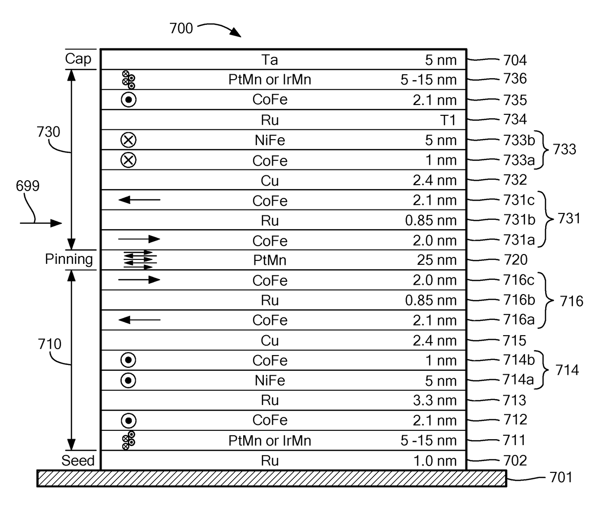
This patent describes a new type of magnetoresistance element and magnetic field sensor that has a wider range of operation compared to conventional magnetoresistance elements. This is achieved by the magnetoresistance element having two stack parts that have different linear responses to magnetic fields of different strengths. This results in a greater range of magnetic field strengths that can be detected with the new technology.

Problems solved by technology

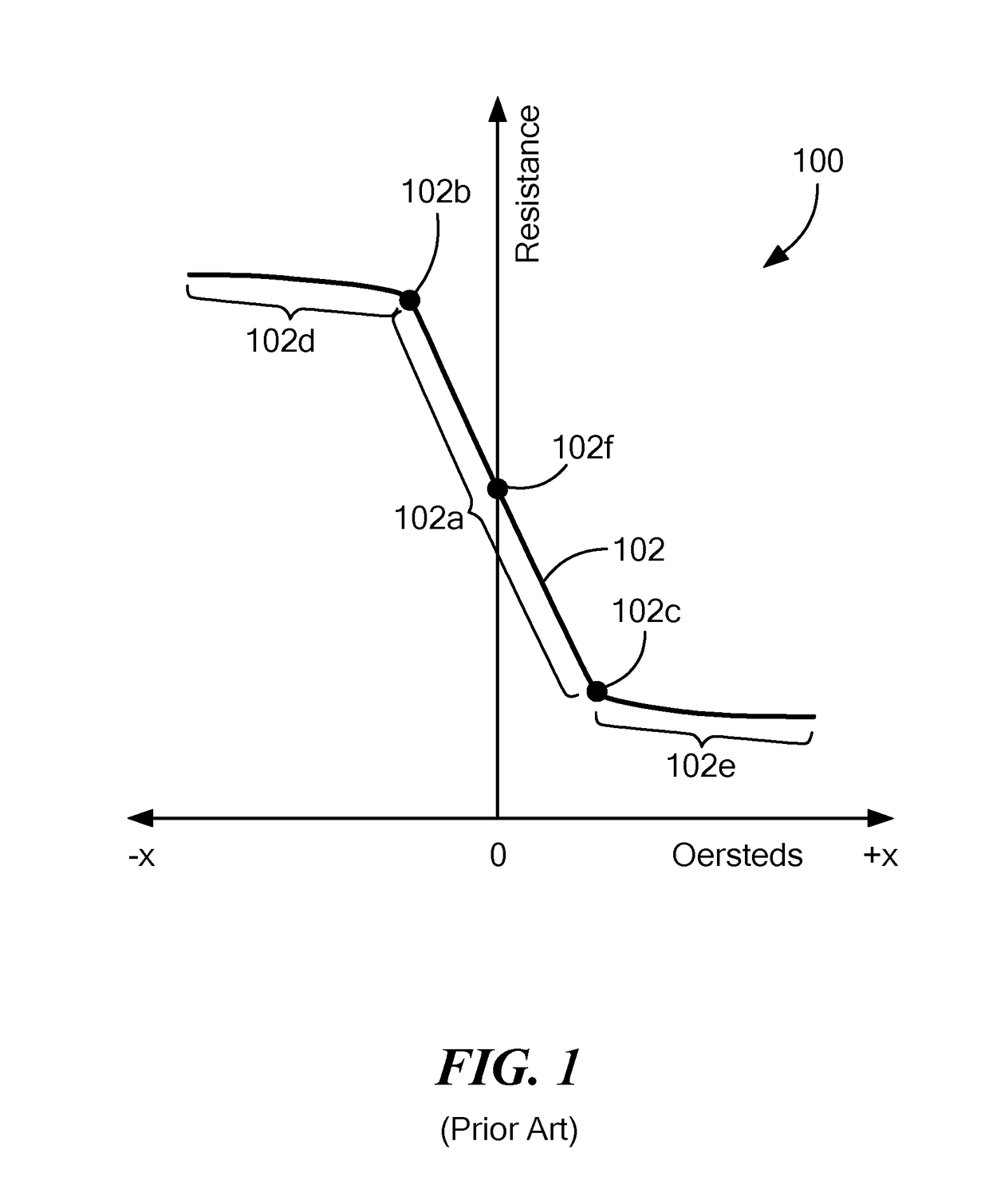
Additionally, an operational range of a circuit or sensor (e.g., a magnetic field sensor) using the magnetoresistance element (i.e., a range in which the circuit or sensor using the magnetoresistance element is capable of generating a signal indicative of the applied magnetic field) may be limited to the operational range of the magnetoresistance element.
For at least the above reasons, the fundamental usage for conventional magnetoresistance elements, and circuits or sensors using conventional magnetoresistance elements, has typically been limited to applications in which sensing is needed over a restricted range of magnetic fields (e.g., low strength magnetic fields) and the relatively high sensitivity characteristics of magnetoresistance elements are desired.

Method used


Image

  • Magnetoresistance element with increased operational range
  • Magnetoresistance element with increased operational range
  • Magnetoresistance element with increased operational range

Examples


Embodiment Construction

[0035]The features and other details of the concepts, systems, and techniques sought to be protected herein will now be more particularly described. It will be understood that any specific embodiments described herein are shown by way of illustration and not as limitations of the disclosure and the concepts described herein. Features of the subject matter described herein can be employed in various embodiments without departing from the scope of the concepts sought to be protected. Embodiments of the present disclosure and associated advantages may be best understood by referring to the drawings, where like numerals are used for like and corresponding parts throughout the various views. It should, of course, be appreciated that elements shown in the figures are not necessarily drawn to scale. For example, the dimensions of some elements may be exaggerated relative to other elements for clarity.

[0036]For convenience, certain concepts and terms used in the specification are provided. ...


PUM


Abstract

A magnetoresistance element deposited upon a substrate includes a first stack portion having opposing first and second surfaces and including a first plurality of layers. The first stack portion has a first substantially linear response corresponding to an applied magnetic field over a first magnetic field strength range. The magnetoresistance element also includes a second stack portion having opposing first and second surfaces and including a second plurality of layers. The first surface of the second stack portion is disposed over the second surface of the first stack portion and the second stack portion has a second substantially linear response that is different than the first substantially linear response. The second substantially linear response corresponds to the applied magnetic field over a second magnetic field strength range.

Description

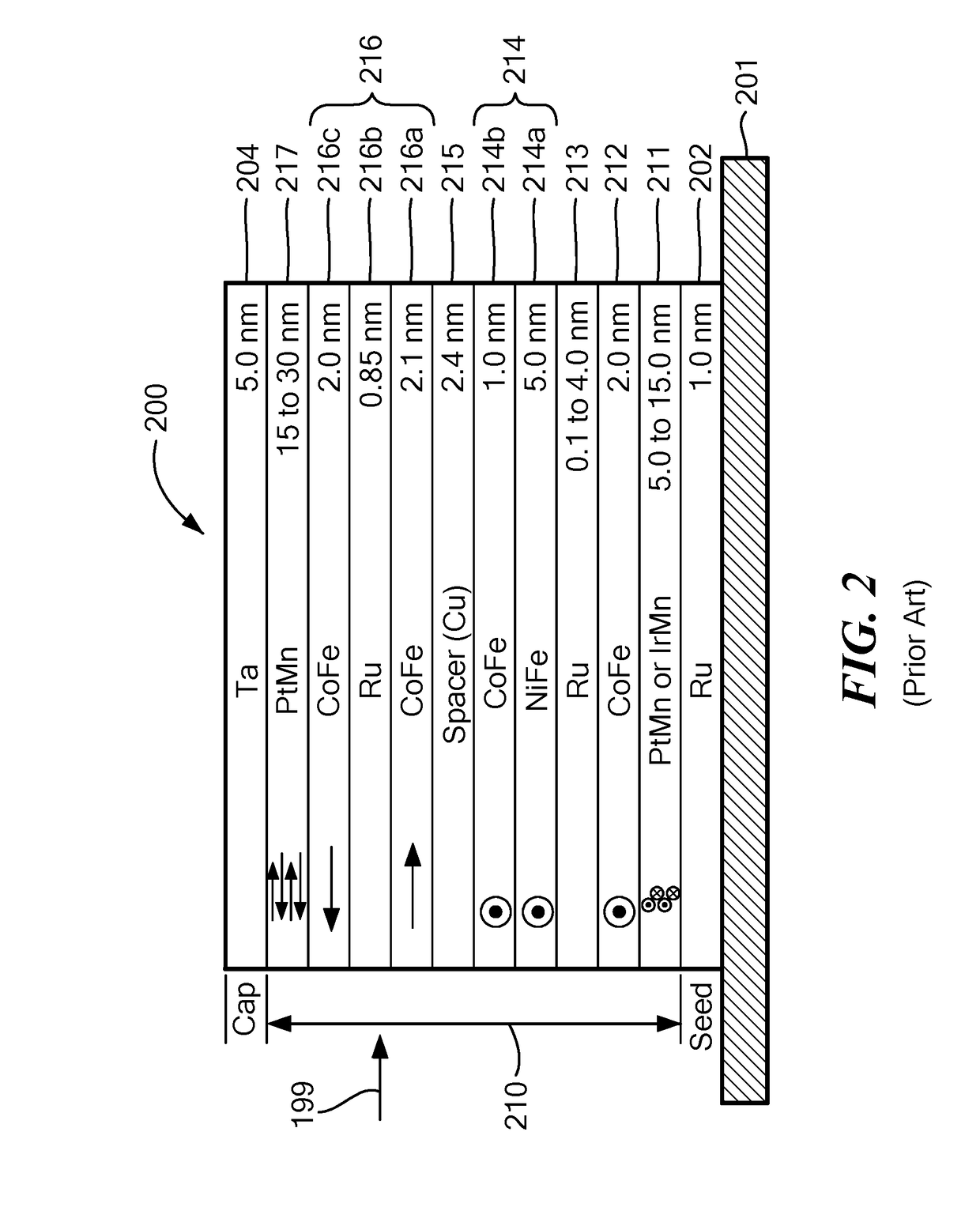
BACKGROUND[0001]As is known in the art, magnetic field sensing elements can be used in a variety of applications. In one example application, a magnetic field sensing element can be used to detect motion (e.g., rotation) of an object, such as a gear or ring magnet. A magnetic field affected by motion of the object may be detected by one or more magnetic field sensing elements, such as Hall effect elements and / or magnetoresistance elements, which provide a signal (i.e., a magnetic field signal) in response to an applied magnetic field. Motion of the object may, for example, result in variations in an air gap between the object (or target features of the object) and the magnetic field sensing elements, which may result in variations in the applied magnetic field to which the magnetic field sensing elements are exposed, and in the magnetic field signals provided by the magnetic field sensing elements in response to the applied magnetic field. Such magnetic field signals can be processe...

Claims


Application Information

Patent Timeline
Patent Type & Authority Applications(United States)
IPC IPC(8): G01R33/09
CPCG01R33/093G01R33/098G01R33/0005
Inventor CAMPIGLIO, PAOLOEAGEN, JEFFREY
Owner ALLEGRO MICROSYSTEMS INC
Learn More