
Wire grid polarizer manufacturing methods using frequency doubling interference lithography

Active Publication Date: 2018-11-22
APPLIED MATERIALS INC
View PDF3 Cites 0 Cited by
  • Summary
  • Abstract
  • Description
  • Claims
  • Application Information

AI Technical Summary

Benefits of technology

This patent describes a method of manufacturing wire grid polarizers (WGP) by using a special exposure system and a process of double development. This method allows for the creation of WGP with smaller distances between the wires, which improves performance. The resulting WGP have finer pitch, meaning the wires are closer together, and increased frequency.

Problems solved by technology

However, polarizing films are very costly.
In fact, polarizing films often account for more than 30% of the total cost of an LCD panel.
Minor energy is lost due to heating in the wires and the rest of the wave is reflected backwards along the incident light beam.
As device dimensions continue to shrink and consumer demand for better resolution devices continues to increase, WGP production techniques for these applications becomes more complicated because the wire grid needs to be more thin and have reduced feature pitch in order to avoid affecting the LED's efficiency or the display's color resolution.

Method used


Image

  • Wire grid polarizer manufacturing methods using frequency doubling interference lithography
  • Wire grid polarizer manufacturing methods using frequency doubling interference lithography
  • Wire grid polarizer manufacturing methods using frequency doubling interference lithography

Examples


Embodiment Construction

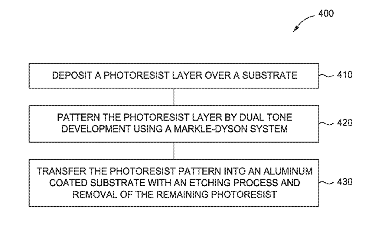
[0025]The present disclosure generally relates to methods and systems for manufacturing wire grid polarizers (WGP) using Markle-Dyson exposure systems and dual tone development (DTD) frequency doubling. In one embodiment, the method includes depositing a photoresist layer over an aluminum-coated display substrate, patterning the photoresist layer by dual tone development using a Markle-Dyson system to form a photoresist pattern, and transferring the photoresist pattern into the aluminum-coated display substrate to manufacture a WGP having finer pitch, for example less than or equal to about 100 nm, and increased frequency.

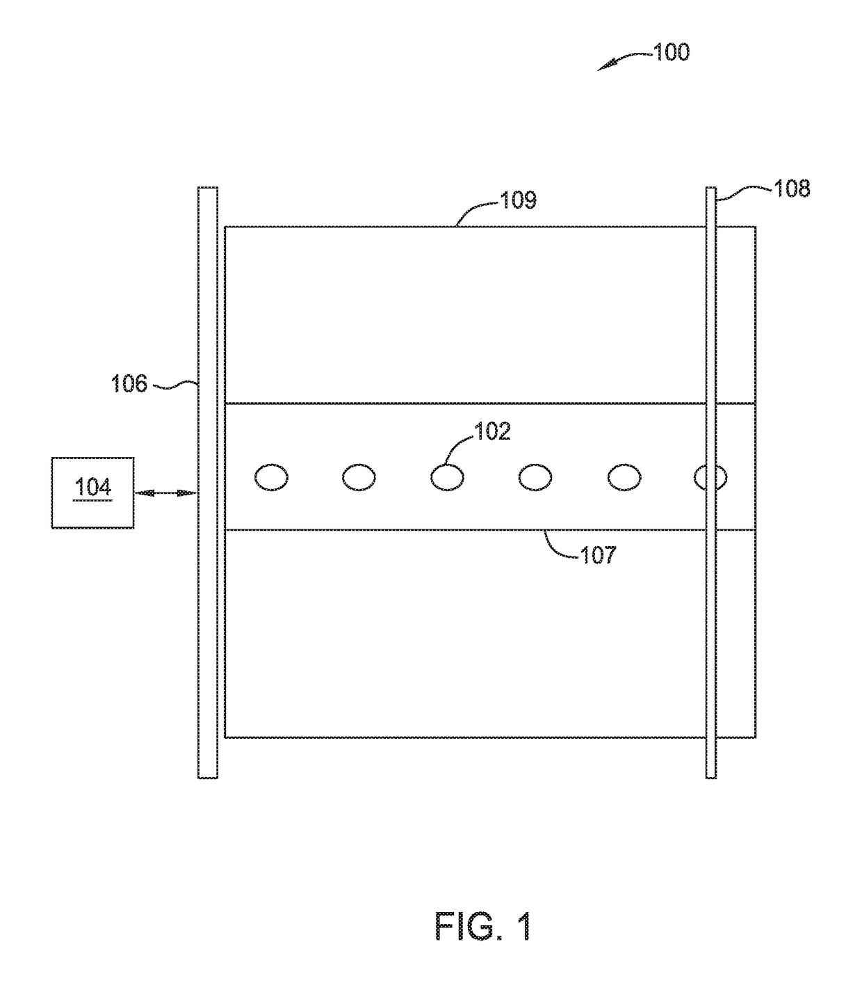
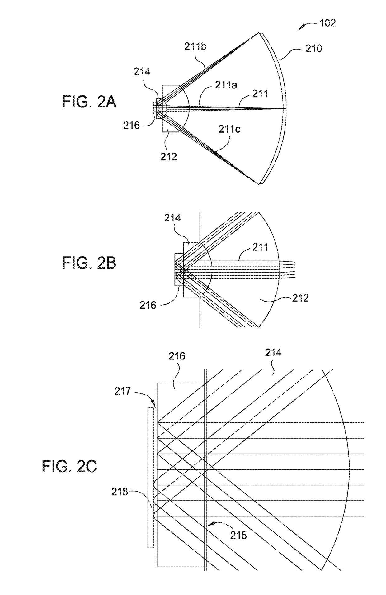
[0026]FIG. 1 is a system 100 for printing a WGP pattern onto a flat panel display substrate. The system 100 includes a plurality of Markle-Dyson (or “half Dyson”) exposure systems 102 (six are shown), a laser gage 104, a laser gage mirror 106 and a substrate stage 109. The plurality of Markle-Dyson exposure systems 102 are generally evenly distributed across the wi...


PUM


Abstract

The present disclosure generally relates to methods and systems for manufacturing wire grid polarizers (WGP) using Markle-Dyson exposure systems and dual tone development (DTD) frequency doubling. In one embodiment, the method includes depositing a photoresist layer over an aluminum-coated display substrate, patterning the photoresist layer by dual tone development using a Markle-Dyson system to form a photoresist pattern, and transferring the photoresist pattern into the aluminum-coated display substrate to manufacture a WGP having finer pitch, for example less than or equal to about 100 nm, and increased frequency.

Description

CROSS-REFERENCE TO RELATED APPLICATIONS[0001]This application claims benefit of U.S. Provisional Patent Application Ser. No. 62 / 506,662, filed on May 16, 2017, which is herein incorporated by reference in its entirety.BACKGROUNDField[0002]Embodiments of the present disclosure generally relate to flat panel display manufacturing processes. More specifically, systems and methods for manufacturing wire grid polarizers for liquid crystal displays (LCDs) are disclosed.Description of the Related Art[0003]An LCD is a display that uses the light-modulating properties of liquid crystals sandwiched between crossed polarizers to display images. LCDs are used in a wide range of applications, including, but not limited to, high definition televisions, computer monitors, and mobile devices. In a typical LCD, the liquid crystal cells are aligned between two linear polarizers, which are oriented orthogonally to one another such that their optical axes are crossed. The polarizers are used to enhance...

Claims


Application Information

Patent Timeline
IPC IPC(8): G03F7/00G02B5/30G02F1/1335
CPCG03F7/0002G02B5/3058G02F1/133528G02F2001/133548G03F7/70408G02F1/133548
Inventor CHEN, JANG FUNGBENCHER, CHRISTOPHER DENNISMARKLE, DAVID
Owner APPLIED MATERIALS INC
Learn More