Photodetector array and codewheel configuration for flexible optical encoder resolution

Inactive Publication Date: 2008-10-09
AVAGO TECH ECBU IP (SINGAPORE) PTE LTD
View PDF7 Cites 0 Cited by
  • Summary
  • Abstract
  • Description
  • Claims
  • Application Information

AI Technical Summary

Benefits of technology

[0005]An optical encoder includes a coding element having a track with multiple transparent sections, a light source positioned to output light to the track, and a photodetector array, positioned to detect light that passes through the transparent sections of the track. The photodetectors of the photodetector array are configured to have larger width dimensions than t

Problems solved by technology

However, using an interpolation IC in this way may require a new PCB layout (due to the additional interpolation IC component) and package redesign.
Typically, this i

Method used


Image

  • Photodetector array and codewheel configuration for flexible optical encoder resolution
  • Photodetector array and codewheel configuration for flexible optical encoder resolution
  • Photodetector array and codewheel configuration for flexible optical encoder resolution

Examples


Example

[0016]Throughout the description similar reference numbers may be used to identify similar elements.

DETAILED DESCRIPTION OF THE INVENTION

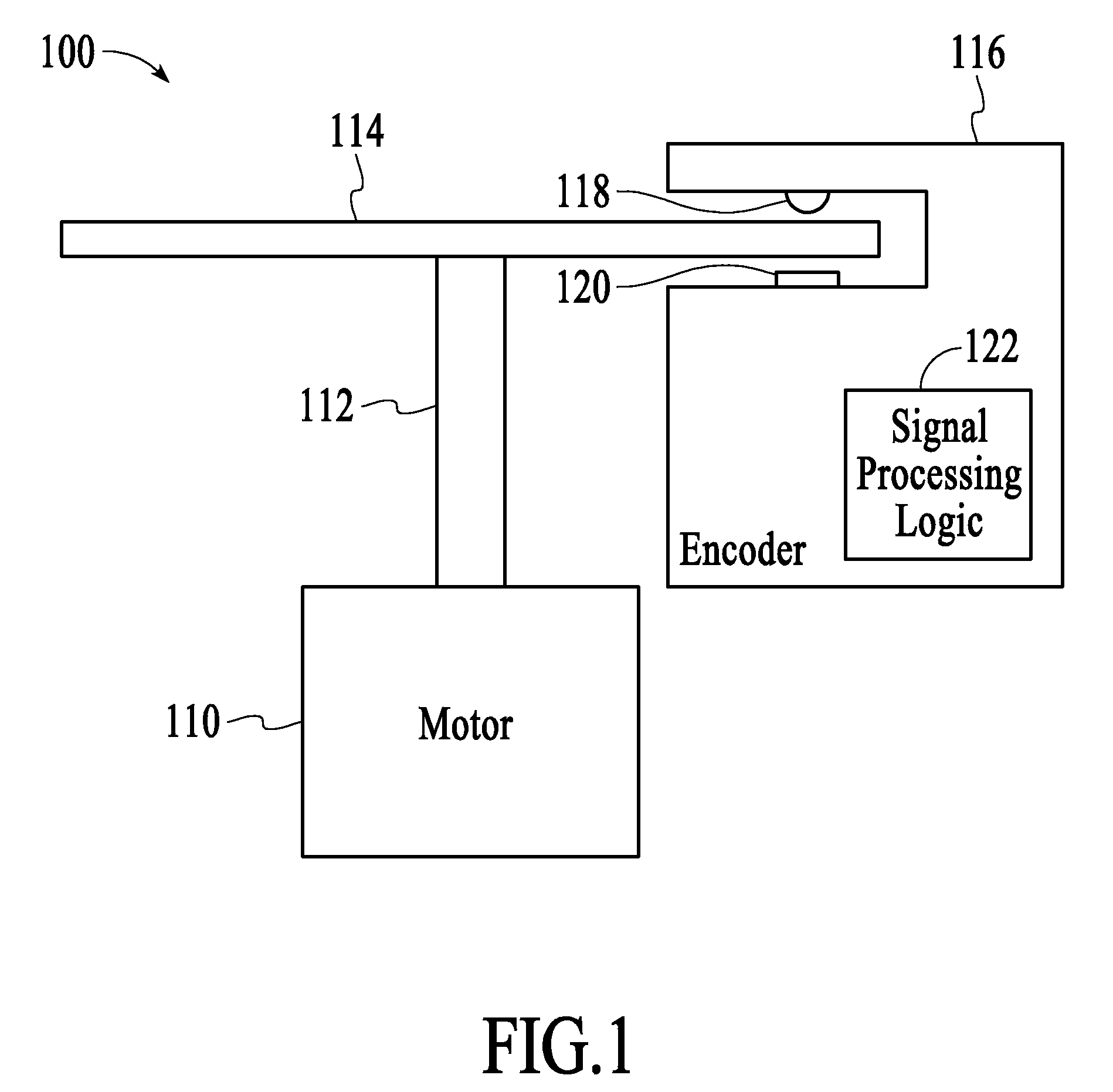
[0017]FIG. 1 depicts an optical encoder system 100 for measuring the rotational movement of a shaft. The optical encoder system includes a motor 110, a shaft 112, a codewheel 114, and an encoder 116. The codewheel includes at least one track (not shown) and the encoder includes a light source 118 of at least one LED and a photodetector array 120 that are aligned with the track. The encoder also includes signal processing logic 122 that processes electrical signals that are output from the photodetector array to measure the rotational movement of the shaft. The motor, shaft, codewheel, and encoder are well-known in the field of optical position encoders. In particular, see U.S. Pat. Nos. 4,451,731, 4,691,101, and 5,241,172, which are incorporated by reference herein.

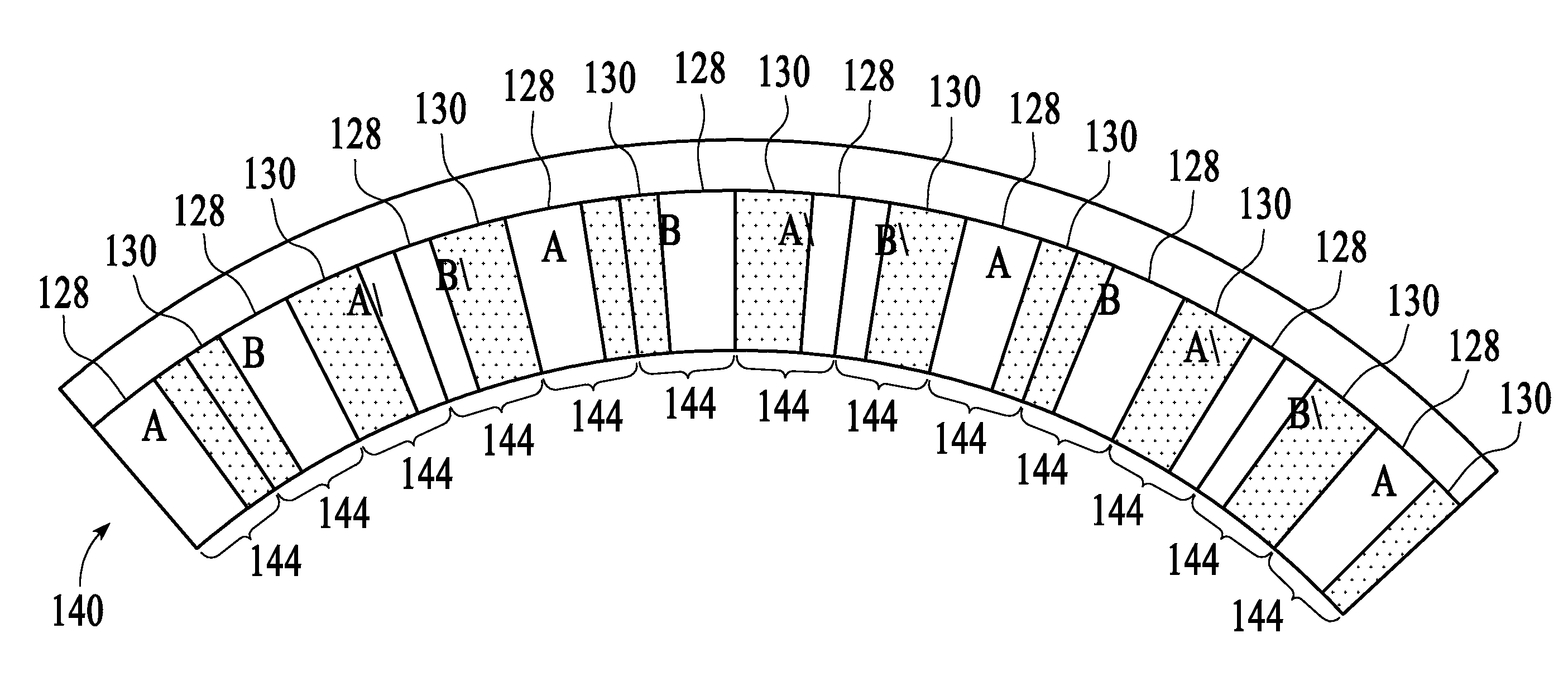
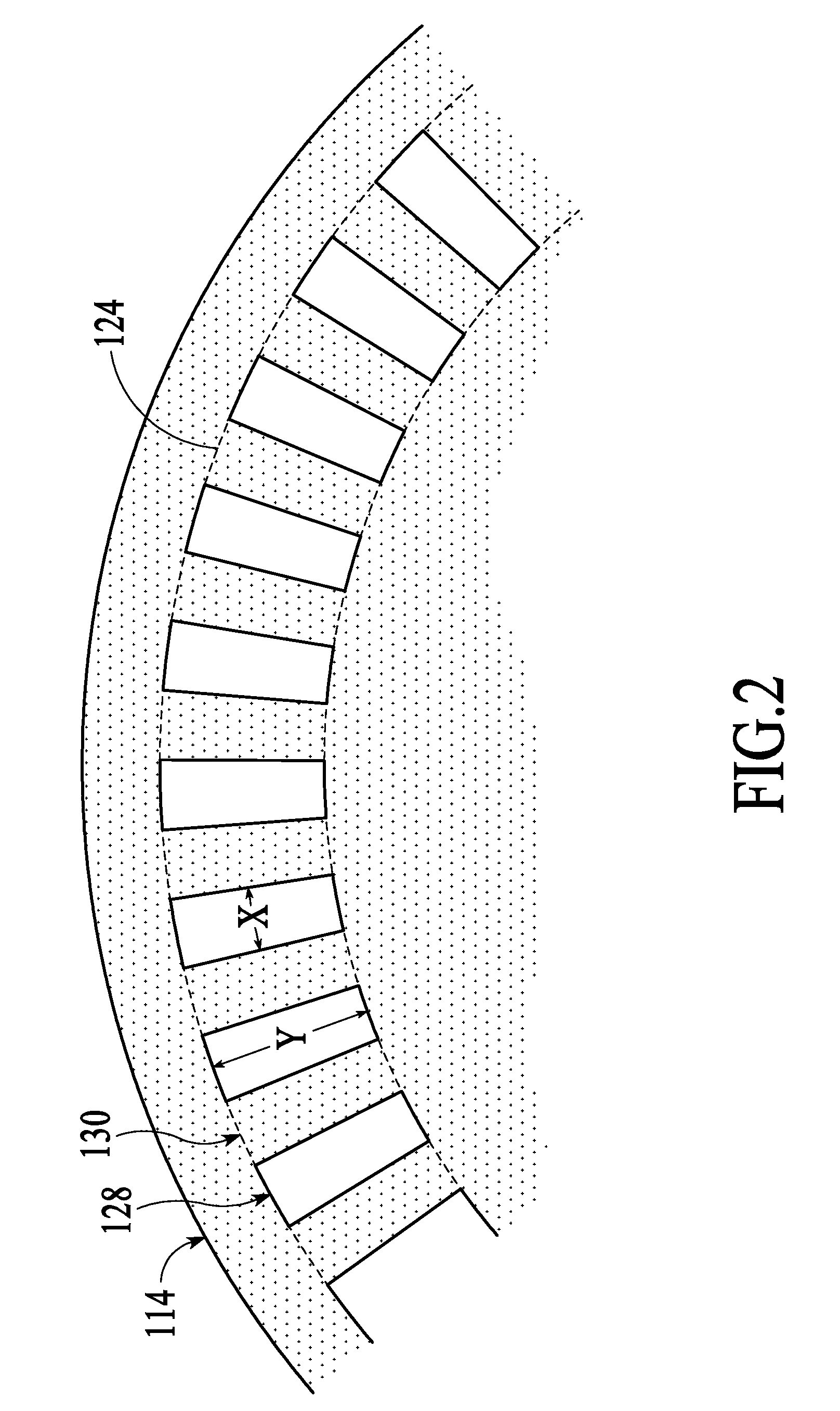
[0018]FIG. 2 depicts a portion of a codewheel 114 that includes a track 124. The tr...


PUM


Abstract

An optical encoder includes a coding element having a track with multiple transparent sections, a light source positioned to output light to the track, and a photodetector array, positioned to detect light that passes through the transparent sections of the track. The photodetectors of the photodetector array have larger width dimensions than the width dimensions of the transparent sections of the track. Resolution of the optical encoder may be adjusted by changing the resolution of the coding element.

Description

CROSS REFERENCE TO RELATED APPLICATIONS[0001]This is a Divisional of co-pending application Ser. No. 10 / 909,482, filed on Aug. 2, 2004, the entire disclosure of which is incorporated herein by reference.BACKGROUND OF THE INVENTION[0002]Optical encoders are used to monitor the motion of, for example, a shaft such as a crankshaft. Optical encoders can monitor the motion of a shaft in terms of position and / or number of revolutions of the shaft. Optical encoders typically use a codewheel attached to the shaft to modulate light as the shaft and the codewheel rotate. The light is modulated as it passes through a track on the codewheel that includes a pattern of transparent and opaque sections. As the light is modulated in response to the rotation of the codewheel, a stream of electrical signals is generated from a photodetector array that receives the modulated light. The electrical signals are used to determine the position and / or number of revolutions of the shaft.[0003]When using an op...

Claims


Application Information

Patent Timeline
IPC IPC(8): G01D5/30
CPCG01D5/3473
Inventor CHONG, CHEE KEONGKHOO, KAY KEATHO, CHI MUN
Owner AVAGO TECH ECBU IP (SINGAPORE) PTE LTD
Why Eureka
Try Eureka