Handover method in mobile communication system

a mobile communication system and technology of handover, applied in the direction of radio transmission, electrical equipment, transmission, etc., can solve the problems of wasting uplink resources, unable to ensure the optimal beam preparation operation at the time of handover execution, and unable to ensure the optimal beam through the corresponding beam, so as to reduce the interruption time of handover, improve service quality, and eliminate the effect of handover interruption

Active Publication Date: 2018-11-22
ELECTRONICS & TELECOMM RES INST
View PDF2 Cites 25 Cited by
  • Summary
  • Abstract
  • Description
  • Claims
  • Application Information

AI Technical Summary

Benefits of technology

[0031]When the target base station supports multiple beams, the terminal transmits the beam measurement result to the target base station through the source base station at the time when the execution of the handover is determined. Accordingly, it is made possible to eliminate a handover interruption time due to a beam refinement procedure, and improve a service quality at the maximum data rate through the maximum beamforming gain as soon as the target base station is connected.
[0032]Also, in order to synchronize handover timings among the terminal, the source base station, and the target base station, the terminal transmits information on a handover time to the target base station through the source base station. Since the source base station can accurately know the handover time of the terminal, the source base station can transmit data to the terminal until the handover time of the terminal. Similarly, since the target base station can accurately know the handover time of the terminal, the target base station can transmit data from the handover time of the terminal. Therefore, the handover interruption time can be minimized and efficient resource utilization becomes possible.

Problems solved by technology

However, in the NR mobile communication system utilizing a high frequency, since a channel state changes rapidly according to movement of the terminal, an optimal beam of the target base station determined during the handover preparation operation may not be an optimal beam at the time of handover execution.
Accordingly, if the terminal accesses to the non-optimal beam at the target base station, or if the channel state of the beam of the target base station is very poor, the handover through the corresponding beam may fail.
However, since the target base station does not know exactly when the terminal executes the handover, the target base station cannot determine from which time point uplink resources should be reserved and until which time point the uplink resources should remain as reserved, and thus there is a problem that the uplink resources are wasted.

Method used


Image

  • Handover method in mobile communication system
  • Handover method in mobile communication system
  • Handover method in mobile communication system

Examples


first embodiment

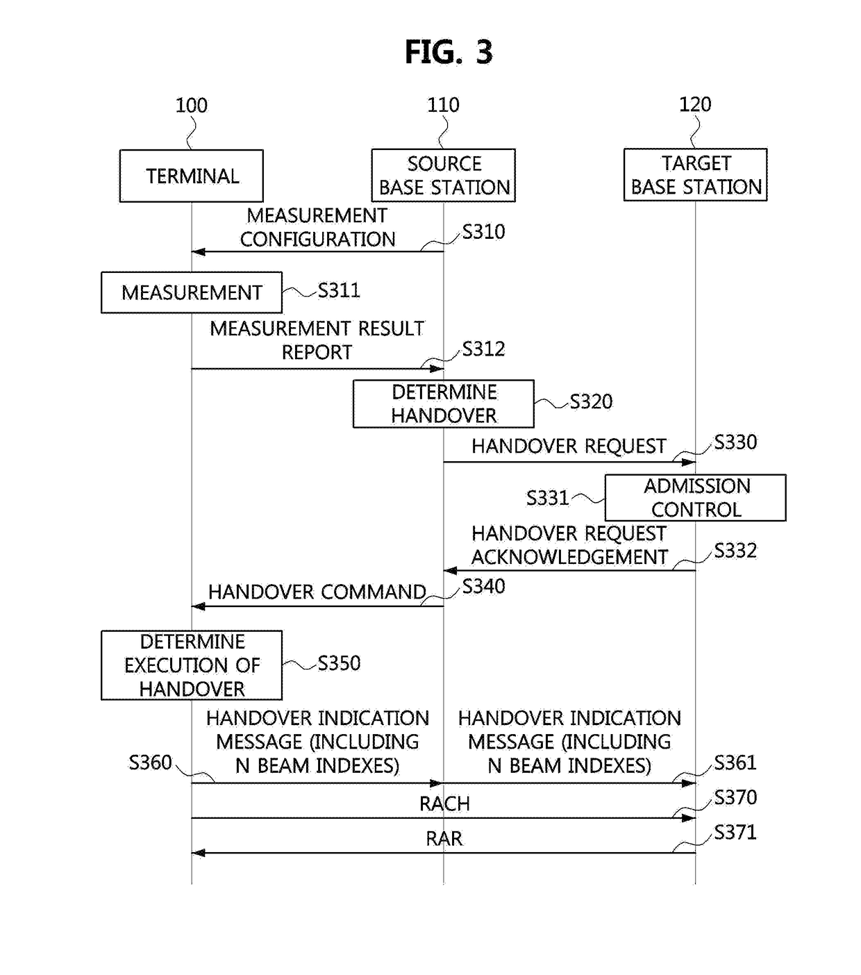
[0071]FIG. 3 is a flow chart for explaining a handover method in a mobile communication system according to the present disclosure.

[0072]The handover method illustrated in FIG. 3 is briefly reconstructed with reference to procedures necessary for explaining the embodiment of the present disclosure, and detailed procedures and subsequent procedures are omitted.

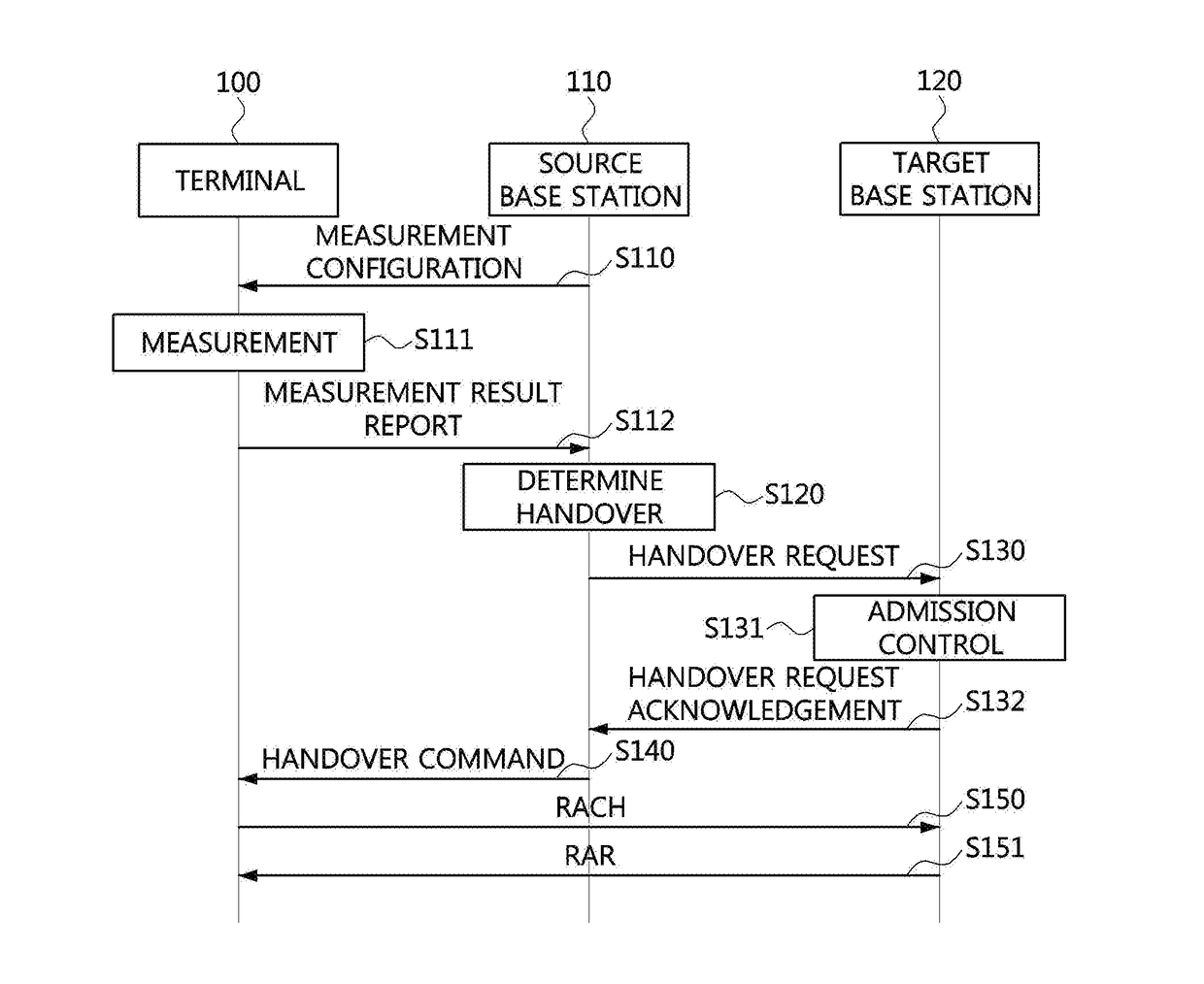
[0073]Referring to FIG. 3, steps S310 to S340 of a handover method according to a first embodiment of the present disclosure may be identical to the steps S110 to S140 constituting the handover method of the general LTE or NR mobile communication system described with reference to FIG. 1.

[0074]That is, the terminal 100 may measure signal strengths of neighbor base stations according to a measurement configuration (S310) of the source base station 110 (S311), and report a measurement result to the source base station (S312). The measurement result may include a cell-level measurement result of the neighbor base stations as well ...

fourth embodiment

[0111]Meanwhile, the uplink resource allocation information received from the target base station may further include information on a start time at which the uplink resources can be used and a validity period during which the uplink resources are valid. This will be described later in the present disclosure with reference to FIG. 13.

[0112]Hereinafter, improvement on the handover interruption time and uplink resource inefficiency illustrated in FIG. 5 will be described with reference to FIG. 7.

[0113]In FIG. 7, descriptions of the same reference numerals as those used in FIG. 5 are omitted, and the assumption on the interface (e.g., X2 interface) latency between the source base station and the target base station, the handover request acknowledgement message processing time of the source base station, the time required for the base station to receive the handover command message, and the handover command message processing time of the terminal are also the same as those of FIG. 5.

[01...

second embodiment

[0123]Also in this case, the handover timing synchronization scheme of the handover method according to the present disclosure described above may be applied, so that an interruption time due to the role change can be completely eliminated.

[0124]For example, in the process of changing roles of MeNB and SeNB, relocation of Packet Data Convergence Protocol (PDCP) layers 811 and 821 may occur and security keys for them should be changed. That is, a state transition should occur from a state in which the PDCP layer 821 of the first base station 810 performs the PDCP layer functions of both the first base station 810 and the second base station 820 to a state in which the PDCP layer 821 of the second base station 820 performs the PDCP layer functions of both the first base station 810 and the second base station 820.

[0125]Since the first base station 810 and the second base station 820 do not know the exact time at which the terminal 830 performs the actual role change, the first base st...


PUM


Abstract

An operation method of a terminal, for a handover in a mobile communication system, may comprise performing measurement on beams of a target base station, and transmitting a measurement result of at least one beam of the target base station to a source base station; receiving, from the source base station, a handover command message including information on at least one RACH resource for the at least one beam; transmitting a handover indication message including information on at least one random access target beam having an order of channel conditions determined based on a latest measurement to the source base station and to the target base station through the source base station; and determining an optimal beam among the at least one random access target beam, and transmitting a RACH to the target base station through a RACH resource allocated to the optimal beam.

Description

CROSS-REFERENCE TO RELATED APPLICATIONS[0001]This application claims priorities to Korean Patent Applications No. 10-2017-0062563 filed on May 19, 2017, No. 10-2017-0078800 filed on Jun. 21, 2017, and No. 10-2018-0050914 filed on May 2, 2018 in the Korean Intellectual Property Office (KIPO), the entire contents of which are hereby incorporated by reference.BACKGROUND1. Technical Field[0002]The present disclosure relates to handover technologies in a mobile communication system, and more specifically, to handover methods for reducing a handover interruption time in a mobile communication system.2. Related Art[0003]The 3rd Generation Partnership Project (3GPP) is in the process of standardizing New Radio (NR), which is a new radio access technology (RAT) for 5G mobile communications. In the NR, a handover procedure is performed as a network-controlled handover procedure based on the long-term evolution (LTE) handover procedure. That is, a source base station may determine a target bas...

Claims


Application Information

Patent Timeline
Patent Type & Authority Applications(United States)
IPC IPC(8): H04W36/08H04W74/08H04W36/00
CPCH04W88/08H04W36/08H04W74/0833H04W36/0083H04B7/0695H04W36/0077H04W36/0058
Inventor PARK, HYUN SEOLEE, HYUNKIM, TAE JOONGLEE, HEE SOOLEE, YU ROKIM, EUN KYUNGLEE, AN SEOK
Owner ELECTRONICS & TELECOMM RES INST
Why Eureka
Try Eureka