
Integrated shoe support structure combining heel counter and shank

a technology of integrated support structure and heel counter, which is applied in the field of footwear, can solve the problems of rigidity, rigidity and weight, and the inability of the heel counter to provide mid-foot rigidity,

Inactive Publication Date: 2018-12-06
CASCA DESIGNS INC
View PDF3 Cites 0 Cited by
  • Summary
  • Abstract
  • Description
  • Claims
  • Application Information

AI Technical Summary

Benefits of technology

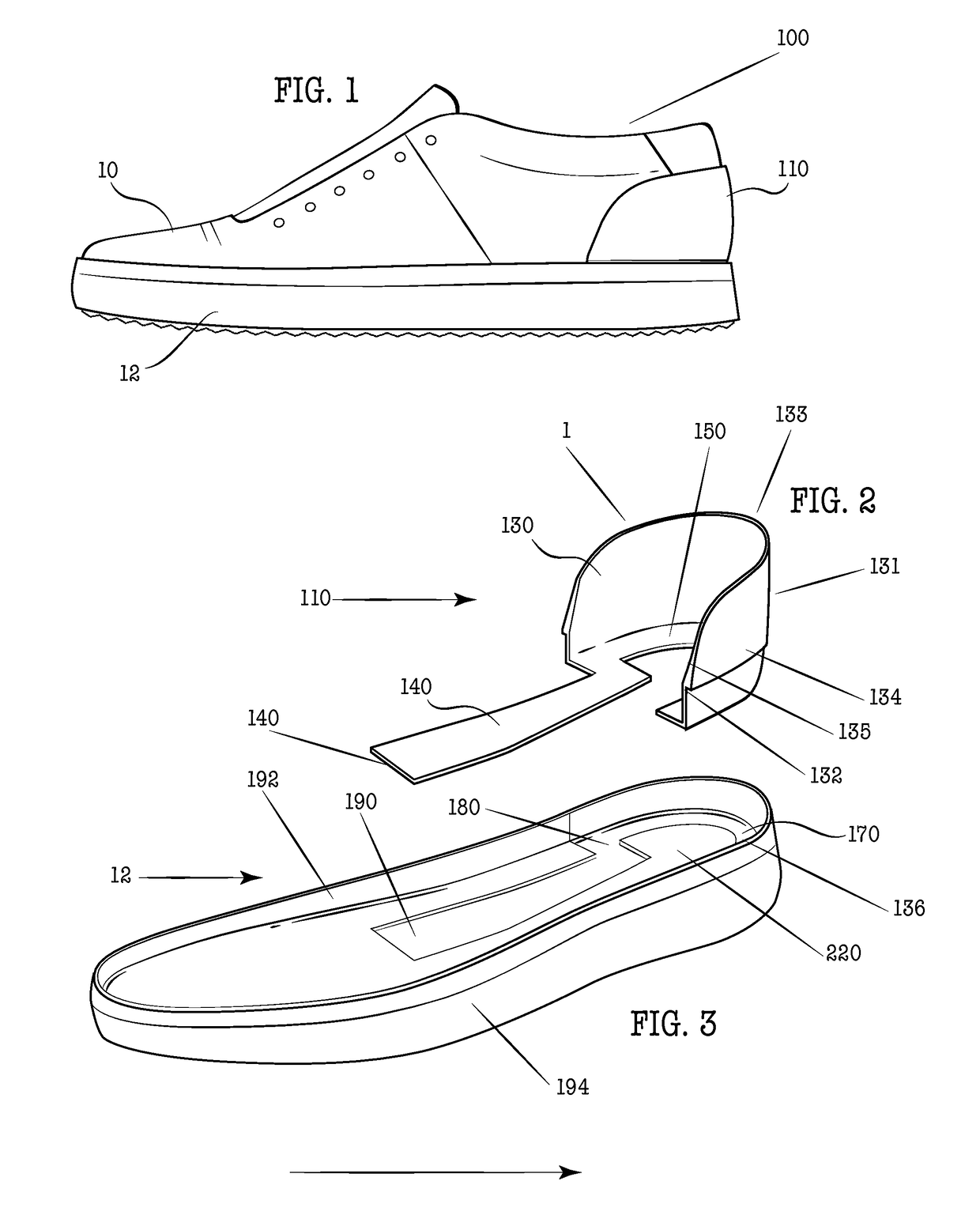
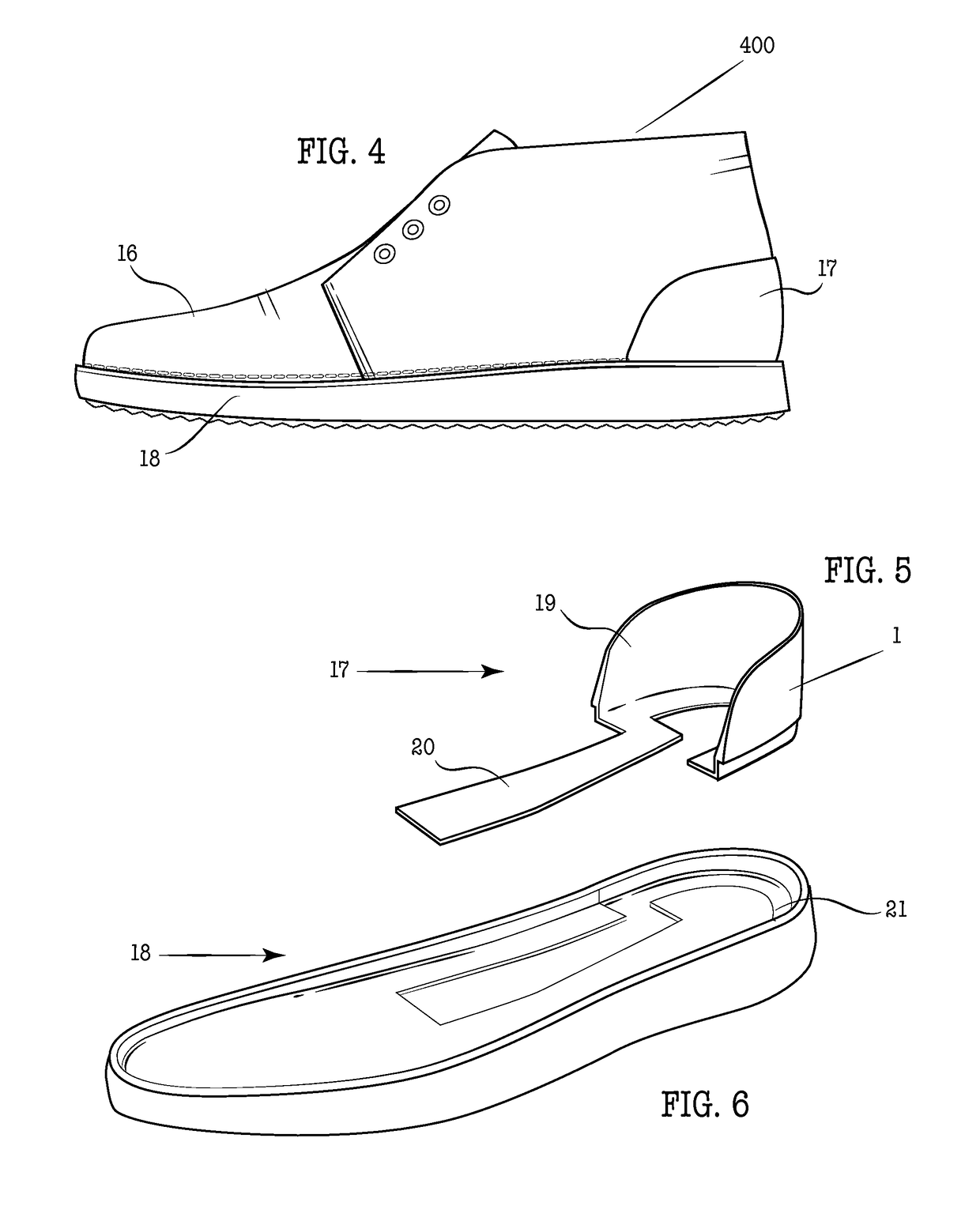
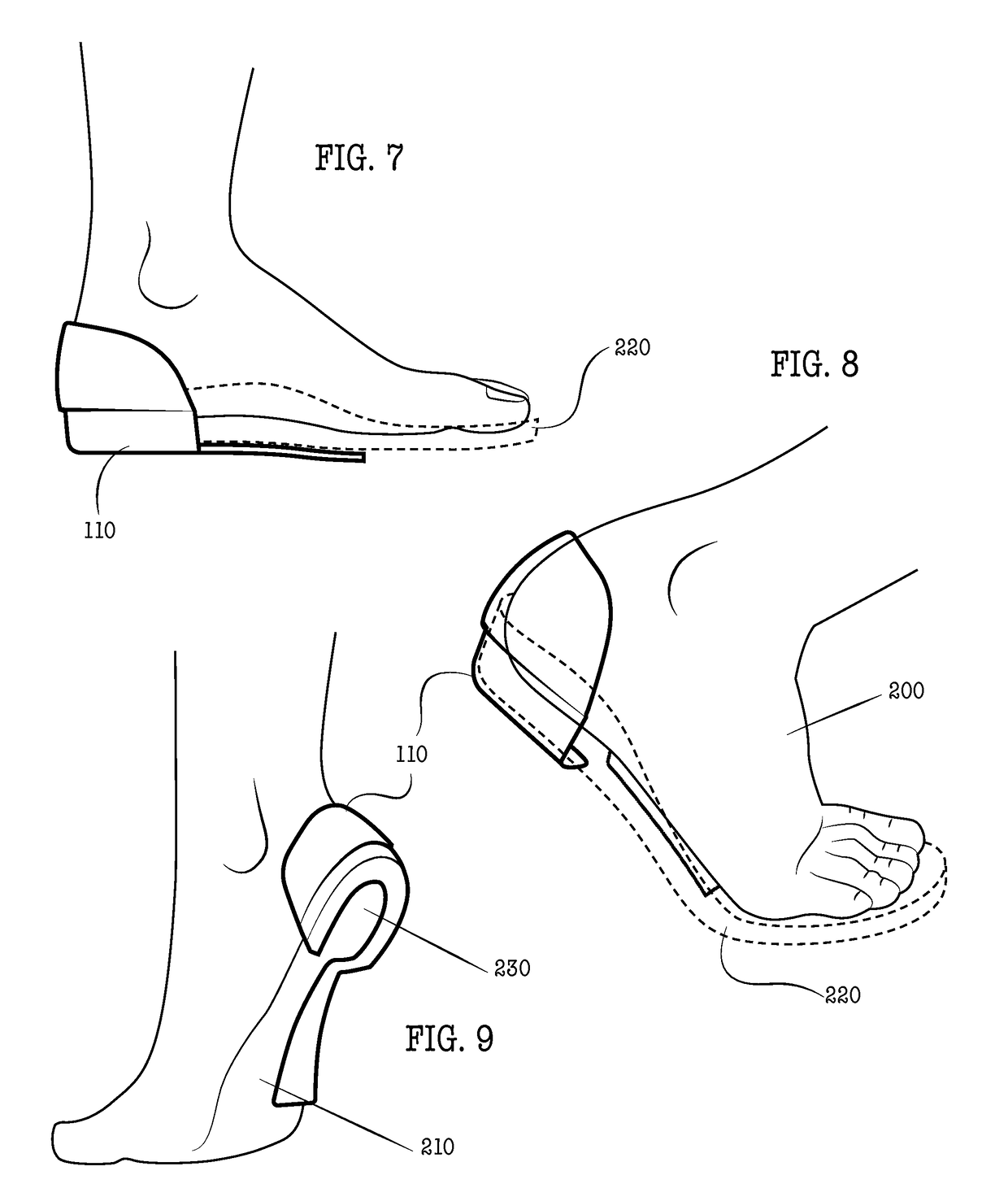
The following is a description of a new type of casual shoe with an external heel counter that provides better stability, comfort, and prevents blistering. The shoe has a unique design that includes a molded shank that connects from the medial side, leaving the lateral side of the foot open to torsional movement while forming a narrow and lightweight support structure running down the center of the midfoot towards the ball. The external heel counter member is securely attached to the sole of the shoe for increased strength and stability. The shoe also has superior cushioning and wear characteristics, with a midsole / insole layer extending throughout the length of the foot and an outer sole layer of harder material than the midsole layer.

Problems solved by technology

However, in these cases, the shoes do not provide mid-foot rigidity through the use of an integrated shank.
Locking the heel into place with a heel counter only solves the issue of lateral stability, but does not stiffen the heel and midfoot, a common practice for work boots and all-day comfort footwear.
A heel counter in combination with a panel that spans the entire surface area under the foot bed is overly stiff, rigid and weighty for this application.
However, no one has suggested the use of an external heel counter extending around both sides of the heel in combination with a support shank that runs under the metatarsal bones, along the center of the underfoot as a single unit connecting from the medial side of the heel counter.

Method used


Image

  • Integrated shoe support structure combining heel counter and shank
  • Integrated shoe support structure combining heel counter and shank
  • Integrated shoe support structure combining heel counter and shank

Examples


Embodiment Construction

[0024]The specific details of the single embodiment or variety of embodiments described herein are set forth in this application. Any specific details of the embodiments are used for demonstration purposes only and no unnecessary limitation or inferences are to be understood therefrom.

[0025]Any reference to “invention” within this document is a reference to an embodiment of a family of inventions, with no single embodiment including features that are necessarily included in all embodiments, unless otherwise stated. Furthermore, although there may be references to “advantage's” provided by some embodiments, other embodiments may not include those same advantages, or may include different advantages. Any advantages described herein are not to be construed as limiting to any of the claims.

[0026]Before describing in detail exemplary embodiments, it is noted that the embodiments reside primarily in combinations of components related to the system. Accordingly, the system components have ...


PUM

PropertyMeasurementUnit
thicknessaaaaaaaaaa
thicknessaaaaaaaaaa
thicknessaaaaaaaaaa

Abstract

Embodiments are described for a semi-rigid apparatus for use in conjunction with the sole and upper of a shoe or sandal. The apparatus involves a heel stabilizer shank enclosing a portion of the heel, with a shank extension from the medial side, a lightweight support structure running along the bottom of the foot between the outsole and insole stiffening the heel and midfoot. Both elements are made from a single piece of material that can be injection molded, 3D printed, or the like. The purpose of this apparatus is to provide all day comfort, protect the heel from lateral shifting, and stiffen the heel and midfoot for less strain on the foot.

Description

CROSS REFERENCE TO RELATED APPLICATIONS[0001]This application claims priority to U.S. Provisional Application 62 / 515,302 entitled “INTEGRATED SHOE SUPPORT STRUCTURE COMBINING HEEL COUNTER AND SHANK” filed Jun. 5, 2017 which is hereby incorporated by reference in its entirety.FIELD[0002]The present invention relates to the field of footwear, and more specifically to the field of integrated support structures in communication with footwear.BACKGROUND[0003]This invention relates generally to footwear, and more specifically pertains to shoes and the like that include a combined heel counter and shank.[0004]Numerous styles of footwear, constructed of various components and for achieving multiple purposes, have long existed in the prior art. Most of these types of innovations have been in the area of athletic or outdoor shoes. Various styles or modifications to the shoes, as in their heel counters and support systems, to make them more comfortable, more resilient, add support or suitabili...

Claims


Application Information

Patent Timeline
Patent Type & Authority Applications(United States)
IPC IPC(8): A43B23/17
CPCA43B23/17A43B7/24A43B13/41A43B23/22
Inventor REID, KEVINPARKER, BRADEN
Owner CASCA DESIGNS INC
Learn More