

Wearable hand robot
- Summary
- Abstract
- Description
- Claims
- Application Information
AI Technical Summary
Benefits of technology
Problems solved by technology
Method used
Image

Examples
Embodiment Construction
Technical Problem
[0008]The present disclosure has been made to solve the problems mentioned above, and accordingly, it is an objective of the present disclosure to provide a wearable hand robot, which can prevent a user's hand from being scratched by a wire as it is pulled or loosened by an actuator, can be mounted in accordance with the size of a user's hand, and is easy to wash and dry.
Technical Solution
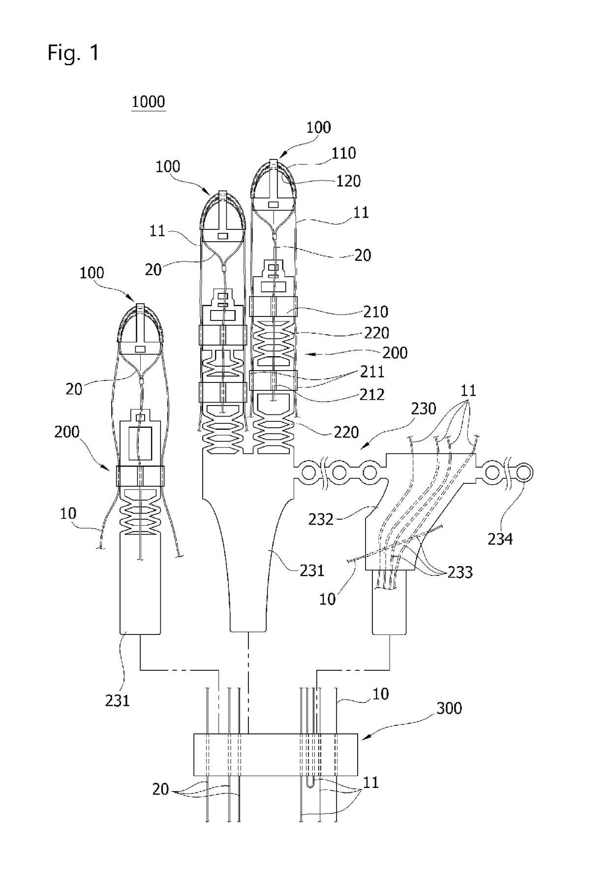
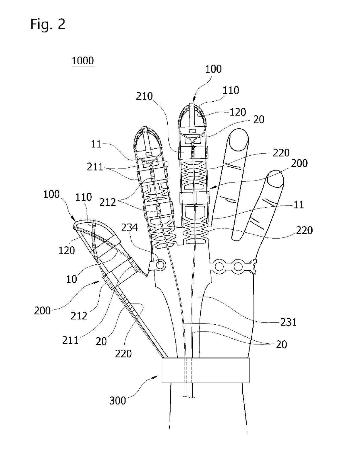
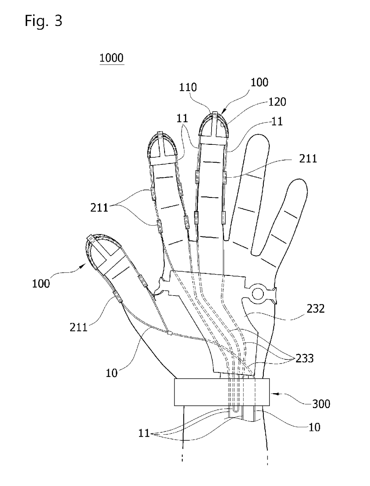
[0009]In order to solve the problems described above, a wearable hand robot is provided, which is a wearable hand robot mounted on a user's fingers and can bend the user's fingers by means of an external force transmitted through a wire, and include at least one first wire which is disposed to extend toward the tip of a finger and then change the extension direction toward the base of the finger; a finger cap which is configured to be fit on the tip of the finger and includes a first wire tube which is disposed at the end of the finger so that the first wire passes therethrough and...
PUM
 Abstract
Description
Claims
Application Information