System and Method for Detecting Broken or Clogged Drainage Pipe Structures

a drainage pipe and structure technology, applied in the direction of service pipe systems, fluid detection at leakage points, mechanical devices, etc., can solve the problems of damage already occurring, failure to achieve the intended purpose, repair or replace the damaged property, etc., and achieve the effect of low power and simple implementation and installation

Inactive Publication Date: 2018-12-06
KELLAR JAMES M
View PDF5 Cites 2 Cited by
  • Summary
  • Abstract
  • Description
  • Claims
  • Application Information

AI Technical Summary

Benefits of technology

[0015]The invention is electrically powered and allows for implementation as a low power solution and may use but not be limited to the use of batteries as a power source avoiding complicated wiring requirements making it simple to implement and install into exist

Problems solved by technology

Eventually all drainage pipe structures experience becoming clogged or broken through any variety of means causing them to fail at their intended purpose.
In most instances this is only discovered when it is too late and damage has already occurred due to fluids and waste materials draining in unintended locations or backing up into bathtubs, sinks, and other fixtures.
When this happens professionals are typically needed to repair or replace the damaged property and can easily become very expensive.
In many cases, as in septic or sewage systems, the fluids and materials to be drained can be hazardous and a backup or flood at the source is potentially dangerous, for example raw sewage.
Detection mechanisms do exist to detect blockages but seem to be rarely seen in commercial and consumer appl

Method used


Image

  • System and Method for Detecting Broken or Clogged Drainage Pipe Structures
  • System and Method for Detecting Broken or Clogged Drainage Pipe Structures
  • System and Method for Detecting Broken or Clogged Drainage Pipe Structures

Examples


Embodiment Construction

[0026]The invention described more fully herein may be embodied in many different forms and should not be construed as limited to the embodiments set forth herein; rather, this embodiment is provided so that this disclosure will satisfy legal requirements. It is understood that various omissions and substitutions of equivalents are contemplated as circumstances may suggest or render expedient, but these are intended to cover the application or implementation without departing from the spirit or scope of the claims of the present invention. Phraseology and terminology used to describe the invention herein is not to be misconstrued as limiting.

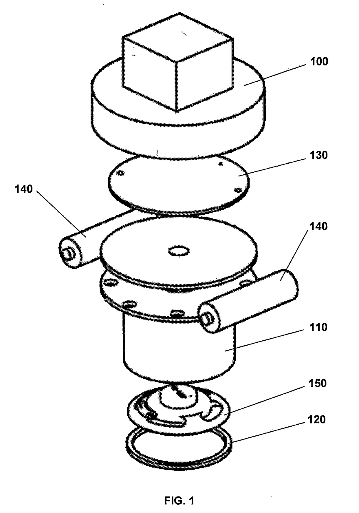
[0027]As shown in FIG. 1. the invention is housed such that it mounts onto a standard sized access port pipe cap, element 100, typical of the field used in septic and sewer drainage systems. A printed circuit board (PCB), element 130 and batteries, elements 140, are mounted toward the upper end of the housing and where the batteries reside in th...


PUM


Abstract

This system and method performs an acoustic scan of a non-pressurized pipe structure typical of septic and sewer systems to detect clogs, line breaks and any structural change in construction. An acoustic scan of the pipe structure is performed periodically by injecting a frequency band limited reference signal into the pipe structure. The pipe structure responds by modulating the reference signal and is representative of the pipe structure's physical construction. The system uses this modulated response to detect variations in the construction of the pipe structure by comparing against a known good calibration standard collected prior. An error score is generated based on the amount of variation from the calibration standard and is compared against a threshold to trigger an alarm condition. If the threshold is exceeded, indicating that a piping issue exists, an alarm is initiated so a user can take appropriate actions to resolve the condition well before a backup or flood begins to occur.

Description

BACKGROUND OF THE INVENTIONReferences[0001]U.S. Pat. No. 9,920,511—Methods, systems and software for providing a blocked sewer alert[0002]U.S. Pat. No. 9,123,230—Sewer backup alarm[0003]U.S. Pat. No. 7,907,059—Sewage pipe alarm system and associated method[0004]U.S. Pat. No. 7,821,411—Safety device for monitoring a conduit[0005]U.S. Pat. No. 5,699,049—Monitoring system for non-pressurized conduit[0006]U.S. Pat. No. 5,687,761—Sewer backup indicator apparatus[0007]U.S. Pat. No. 4,973,950—Sewer blockage alarming[0008]2007 / 0063856—Monitoring system for drain pipes and plumbing fixturesFIELD OF THE INVENTION[0009]The invention relates generally to a detection system for non-pressurized drainage pipe structures. Specifically the invention relates to a detection system that is mounted into a non-pressurized pipe structure and which monitors said pipe structure's physical construction and characteristics such that if any modification of said structure occurred, for example re-plumbing, bloc...

Claims


Application Information

Patent Timeline
IPC IPC(8): F17D5/06G01M3/18
CPCF17D5/06G01M3/18E03F7/00E03B7/071Y02A20/15
Inventor KELLAR, JAMES M.
Owner KELLAR JAMES M
Why Eureka
Try Eureka