

Imaging lens
a technology of imaging lens and spherical lens, which is applied in the field of imaging lens, can solve the problems of insufficient low-profileness, difficult aberration correction in the peripheral area, and inability to obtain excellent optical performance, etc., and achieves effective low-profileness and wide field of view. , the effect of high resolution
- Summary
- Abstract
- Description
- Claims
- Application Information
AI Technical Summary
Benefits of technology
Problems solved by technology
Method used
Image

Examples
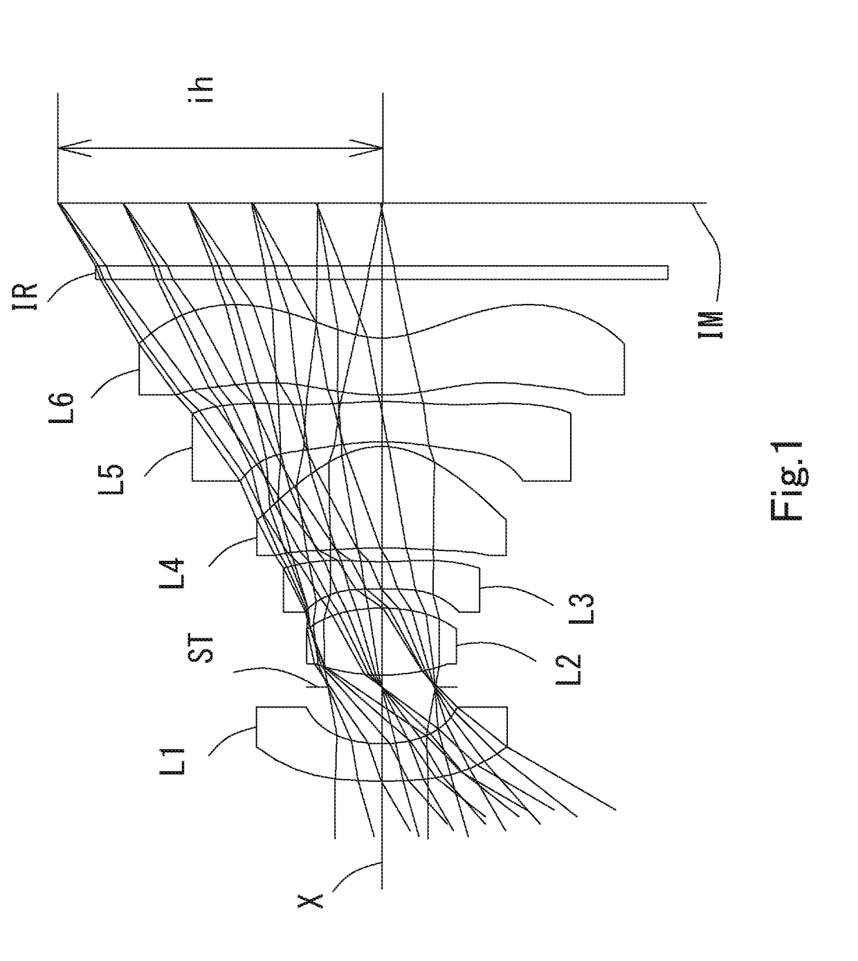
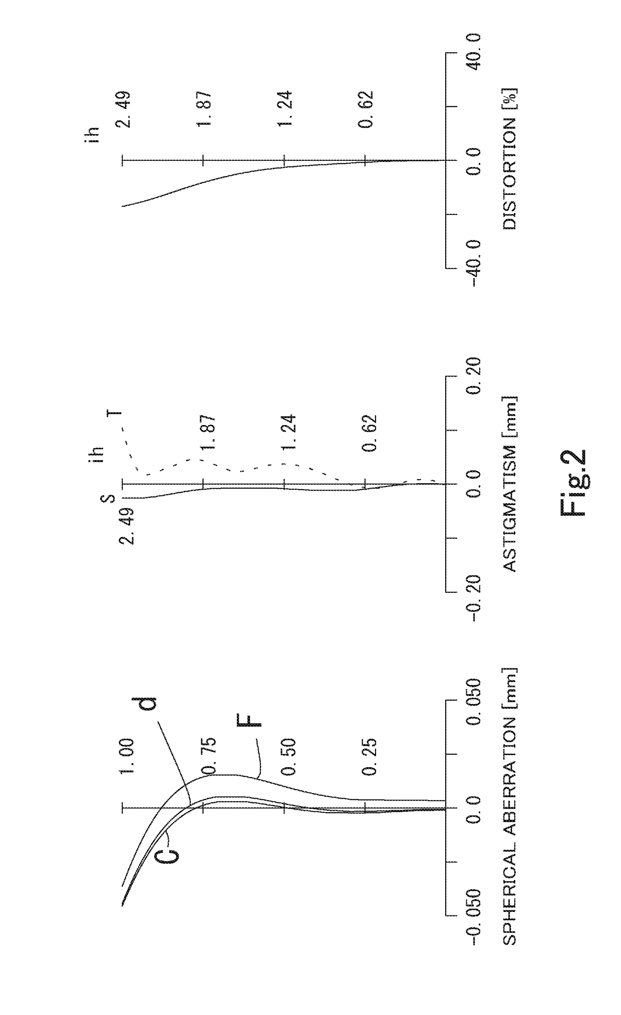
example 1
[0158]The basic lens data is shown below in Table 1.
Example 1Unit mmf = 1.74Fno = 2.42ω (°) = 59.9ih = 2.49TTL = 4.42Surface DataSurfaceCurvatureSurfaceRefractiveAbbe NumberNumber iRadius rDistance dIndex Ndvd(Object)InfinityInfinity 1*6.7720.2881.544355.86 2*1.2050.436 3 (Stop)Infinity0.092 4*1.6340.5151.544355.86 5*−1.5470.149 6*−9.0530.2101.651021.52 7*3.1950.105 8*−4.3350.7821.534855.66 9*−0.6320.03510*−1.9910.3101.639123.2511*−3.5460.05012*1.7780.4401.534855.6613*0.7420.50014Infinity0.1101.516864.2015Infinity0.431Image PlaneInfinityConstituent Lens DataLensStart SurfaceFocal Length11f1 = −2.74f456 = 2.4324f2 = 1.55CA1 = 1.9536f3 = −3.60CA2 = 1.1748f4 = 1.29SAG L1F = 0.27510f5 = −7.70SAG L1R = 0.28612f6 = −2.80Aspheric Surface DataFirst SurfaceSecond SurfaceFourth SurfaceFifth SurfaceSixth SurfaceSeventh Surfacek0.00000E+002.83986E+002.47910E+000.00000E+000.00000E+007.61528E−01A44.40403E−015.83114E−012.74129E−02−6.26256E−01−1.60329E+00−8.70183E−01A6−4.84282E−016.00713E−01−3.7598...
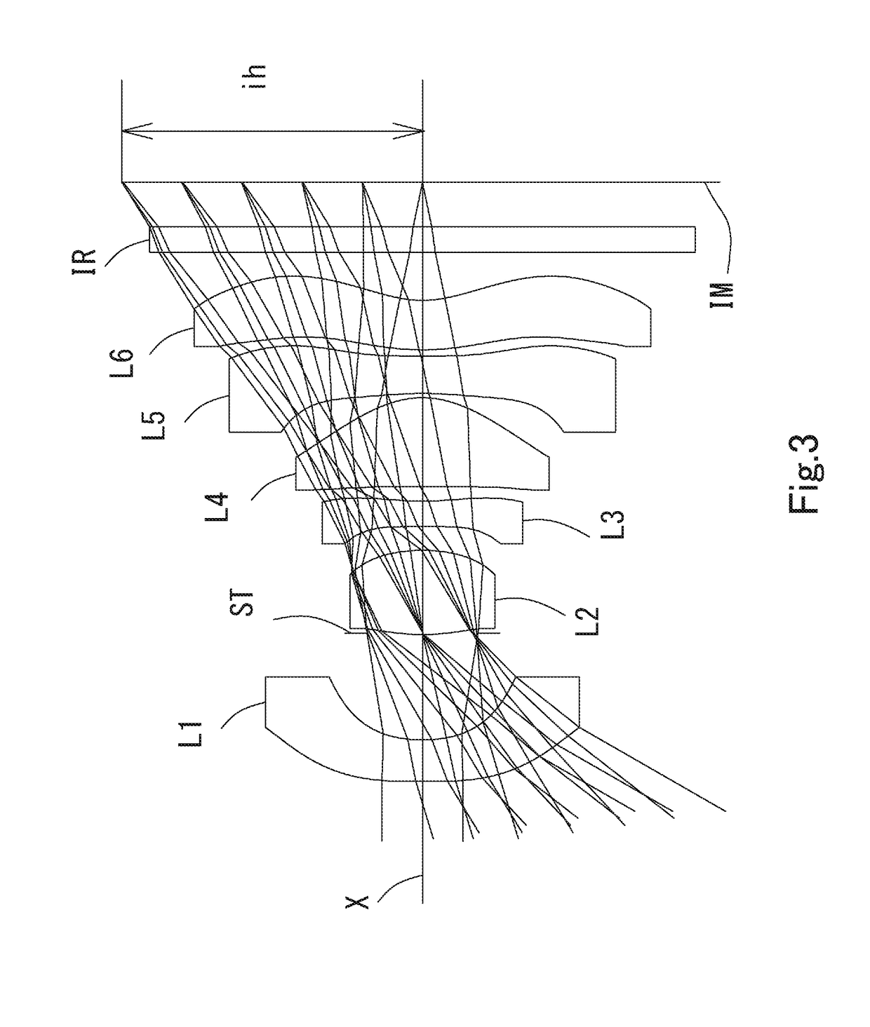
example 2
[0161]The basic lens data is shown below in Table 2.
Example 2Unit mmf = 1.63Fno = 2.39ω (°) = 60.1ih = 2.49TTL = 4.90Surface DataSurfaceCurvatureSurfaceRefractiveAbbe NumberNumber iRadius rDistance dIndex Ndvd(Object)InfinityInfinity 1*11.8090.3451.534855.66 2*1.2020.883 3 (Stop)Infinity−0.009 4*1.8270.6971.544355.86 5*−1.4050.198 6*23.4390.2101.650321.54 7*2.3120.120 8*−159.5980.7371.534855.66 9*−0.7470.03510*−2.9870.3101.639123.2511*82.2360.05112*1.9770.4101.534855.6613*0.8620.25014Infinity0.2101.516864.2015Infinity0.520Image PlaneInfinityConstituent Lens DataLensStart SurfaceFocal Length11f1 = −2.53f456 = 3.1324f2 = 1.58CA1 = 2.6936f3 = −3.96CA2 = 1.5948f4 = 1.40SAG L1F = 0.48510f5 = −4.50SAG L1R = 0.56612f6 = −3.27Aspheric Surface DataFirst SurfaceSecond SurfaceFourth SurfaceFifth SurfaceSixth SurfaceSeventh Surfacek0.00000E+005.31502E−01−3.36243E+000.00000E+000.00000E+004.00696E−01A43.71110E−014.86718E−01−4.24428E−02−4.06448E−01−8.91305E−01−5.97792E−01A6−3.49809E−011.00383E+00−...
example 3
[0164]The basic lens data is shown below in Table 3.
Example 3Unit mmf = 1.89Fno = 2.25ω (°) = 60.0ih = 2.28TTL = 4.57Surface DataSurfaceCurvatureSurfaceRefractiveAbbe NumberNumber iRadius rDistance dIndex Ndvd(Object)InfinityInfinity 1*−1984.0210.5381.534855.66 2*1.9620.629 3 (Stop)Infinity−0.043 4*1.7540.5841.544355.86 5*−2.7540.096 6*−177.0420.2101.650321.54 7*6.4500.110 8*−11.5270.6451.534855.66 9*−0.6660.03510*−2.6400.3101.639123.2511*15.4730.14912*1.9660.3981.534855.6613*0.7730.29014Infinity0.1451.516864.2015Infinity0.525Image PlaneInfinityConstituent Lens DataLensStart SurfaceFocal Length11f1 = −3.67f456 = 3.5624f2 = 2.06CA1 = 3.0036f3 = −9.56CA2 = 1.6248f4 = 1.29SAG L1F = 0.30510f5 = −3.51SAG L1R = 0.34612f6 = −2.69Aspheric Surface DataFirst SurfaceSecond SurfaceFourth SurfaceFifth SurfaceSixth SurfaceSeventh Surfacek0.00000E+000.00000E+000.00000E+000.00000E+000.00000E+000.00000E+00A41.43539E−013.90095E−014.33654E−03−6.46283E−01−8.26642E−01−3.86847E−01A6−8.83772E−02−2.67894E−...
PUM
 Abstract
Description
Claims
Application Information