Data processing apparatus, data processing method, and computer readable medium

a data processing apparatus and data processing technology, applied in the direction of color television details, closed-circuit television systems, television systems, etc., can solve the problem that the monitor camera cannot keep the correct time at power o

Inactive Publication Date: 2018-12-13
MITSUBISHI ELECTRIC CORP
View PDF2 Cites 2 Cited by
  • Summary
  • Abstract
  • Description
  • Claims
  • Application Information

AI Technical Summary

Benefits of technology

[0026]In the present invention, a readout time of I-frame data is calculated based on a reception time of the I-frame data to be read out, a reception time of preceding I-frame data, and a readout time of the preceding I-frame data, so that a displacement of the I-frame data at the reception time can be adjusted.
[0027]Therefore, according to the present invention, even when a size of the I-frame data is larger than that of other types of frame data, a readout time of frame data of each frame can be synchronized with an image capturing time without using specialized hardware.

Problems solved by technology

If the monitor camera that transmits the video data according to the above method does not have a battery for time backup, the monitor camera cannot keep the correct time at power off.

Method used


Image

  • Data processing apparatus, data processing method, and computer readable medium
  • Data processing apparatus, data processing method, and computer readable medium
  • Data processing apparatus, data processing method, and computer readable medium

Examples


first embodiment

[0033]***Description of Configuration***

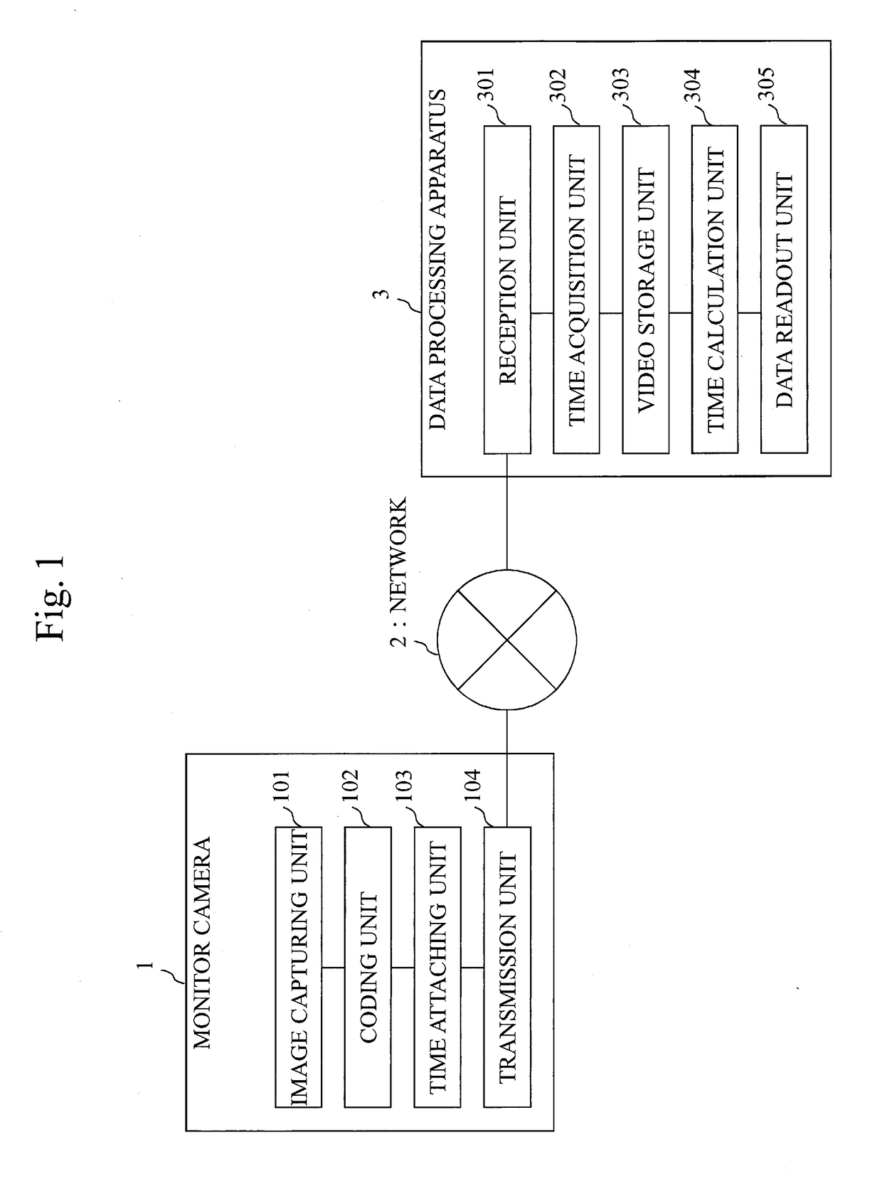
[0034]FIG. 1 illustrates a system configuration example according to the present embodiment.

[0035]In FIG. 1, a monitor camera 1 captures an image of an image capturing target (for example, an area to be monitored), and transmits video data of the image capturing target.

[0036]A network 2 is a network used for transmitting the video data, and is a LAN (Local Area Network), the Internet, or the like.

[0037]A data processing apparatus 3 receives the video data which is from the monitor camera 1, and stores the received video data.

[0038]The data processing apparatus 3 is, for example, a monitor recorder.

[0039]Note that, FIG. 1 illustrates only one monitor camera 1, but there may exist a plurality of monitor cameras 1.

[0040]The captured video data from the monitor camera 1 includes a plurality of pieces of I (Intra-coded)-frame data, a plurality of pieces of B (Bi-directional Predicted)-frame data, and a plurality of pieces of P (Predicted)-frame dat...

second embodiment

[0122]In the first embodiment, the method for calculating the readout time of the P-frame data is the same as the method for calculating the readout time of the B-frame data.

[0123]In the present embodiment, the readout time of the P-frame data is calculated in accordance with the method for calculating the readout time of the I-frame data indicated in the first embodiment.

[0124]In the present embodiment, a system configuration example is also as illustrated in FIG. 1.

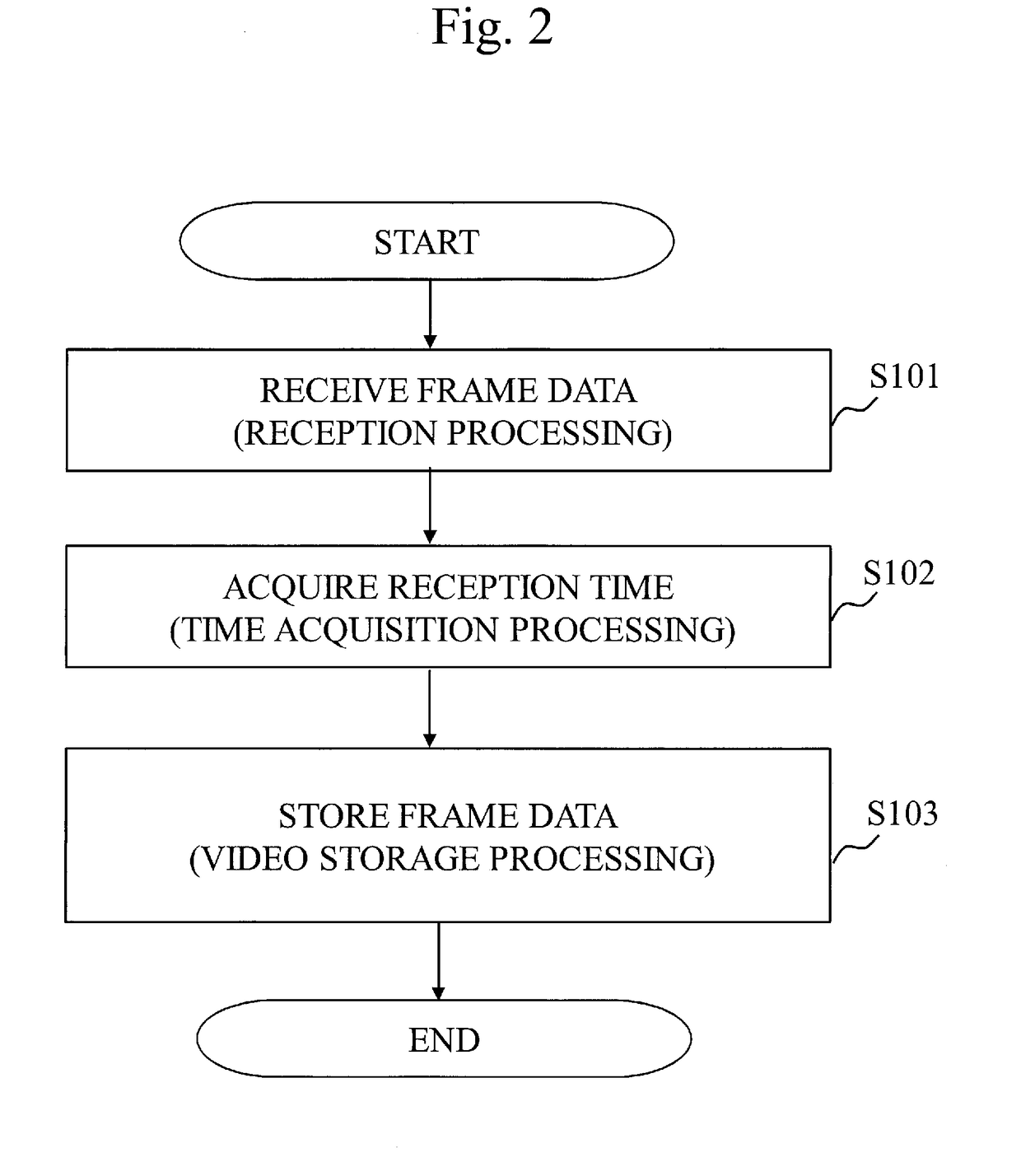
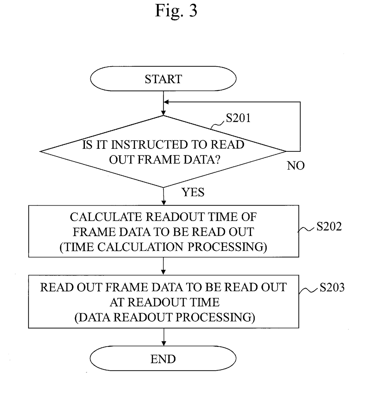
[0125]Further, an operation of the data processing apparatus 3 is also as illustrated in FIGS. 2 and 3.

[0126]However, in the present embodiment, the time acquisition unit 302 acquires, at S102 in FIG. 2, the reception time at which the reception unit 301 receives the I-frame data and also acquires the reception time at which the reception unit 301 receives the P-frame data.

[0127]When one piece of P-frame data is divided into a plurality of RTP packets and the plurality of RTP packets are transmitted, the time acquisitio...


PUM


Abstract

A reception unit (301) receives a plurality of pieces of I-frame data and a plurality of pieces of P-frame data in which time stamps are set. A time acquisition unit (302) acquires a reception time of each I-frame data. A video storage unit (303) stores the plurality of pieces of I-frame data and the plurality of pieces of P-frame data. A time calculation unit (304) calculates a readout time of the I-frame data from the video storage unit (303) based on a reception time of the I-frame data to be read out, a reception time of preceding I-frame data being I-frame data that precedes the I-frame data to be read out, and a readout time of the preceding I-frame data, and calculates a readout time of the P-frame data from the video storage unit (303) based on a time stamp of the P-frame data to be read out. A data readout unit (305) reads out the I-frame data to be read out and the P-frame data to be read out at the times calculated by the time calculation unit (304).

Description

TECHNICAL FIELD[0001]The present invention relates to a technique for controlling a readout time of video data.BACKGROUND ART[0002]Assume a case where a monitor camera transmits the video data to a recorder using a RTP (Real-time Transport Protocol) protocol defined in the RFC (Request for Comments) 3550.[0003]In this case, in the recorder, a time stamp included in a RTP header is synchronized, using a SR (Sender Report) of a RTCP (Real-time Transport Control Protocol) packet, with a NTP (Network Time Protocol) time stamp provided in the monitor camera.[0004]If the monitor camera that transmits the video data according to the above method does not have a battery for time backup, the monitor camera cannot keep the correct time at power off.[0005]Therefore, when the monitor camera is powered off, a time is acquired from the outside using a NTP protocol or the like after power on.[0006]However, the monitor camera needs a predetermined time interval to acquire the time.[0007]When the mo...

Claims


Application Information

Patent Timeline
Patent Type & Authority Applications(United States)
IPC IPC(8): H04L29/06H04N7/18H04N5/232H04N19/172H04N19/159H04N19/114
CPCH04L65/608H04N7/18H04N5/23206H04N19/172H04N19/159H04N19/114H04N21/44H04N7/183H04N21/4344H04N21/44008H04N21/6437H04L65/65H04N23/661
Inventor HIRAMATSU, TAKAHIRO
Owner MITSUBISHI ELECTRIC CORP
Why Eureka
Try Eureka