Pipe layer and warm-up method for pipe layer

a technology of warm-up method and pipe layer, which is applied in the direction of fluid couplings, servomotors, and hoisting equipment, etc., can solve the problems of affecting the opening area, unable to send a suitable amount of hydraulic fluid to a control valve or a throttle, and difficult to fine-tune the opening area using electronically controlled devices such as those described above. , to achieve the effect of reliable warm-up, adequate amount of heat, and guaranteed hydraulic fluid flow ra

Active Publication Date: 2014-12-16
KOMATSU LTD
View PDF19 Cites 0 Cited by
  • Summary
  • Abstract
  • Description
  • Claims
  • Application Information

AI Technical Summary

Benefits of technology

[0009]An object of the present invention is to provide a pipe layer and a warm-up method for a pipe layer that can reliably perform a warm-up even in an extremely cold environment and ensure an adequate amount of heat while holding a state in which the pipe layer is lifting a pipe.
[0014]A pipe layer according to a first aspect of the present invention switches between execution and stoppage of a warm-up by switching the flow channel open / close unit between an open state and a closed state. Thus, fine adjusting of the opening area of the flow channel open / close unit is not required. Since the fine adjusting of the opening area is not required, control of the flow channel open / close unit can be carried out by a hydraulic pressure pilot without relying on an electronic device. As a result, a reliable warm-up can be conducted even in an extremely cold environment. Further, the displacement of the pump is adjusted in the pipe layer so that the differential pressure between the pump hydraulic circuit and the drive hydraulic circuit becomes constant at a predetermined set pressure when the flow channel open / close unit is in the open state. Specifically, when a warm-up is being conducted, the displacement of the hydraulic pump can be adjusted in response to a load pressure on the warm-up hydraulic circuit for warm-up even when the rotational speed of the engine is reduced. Therefore, a hydraulic fluid flow rate required for warm-up can be assured even when the pipe layer stops the hydraulic motor and is holding a pipe in a lifted state. As a result, an adequate amount of heat can be assured while the pipe layer is holding the pipe in the lifted state.
[0016]In a pipe layer according to the third aspect of the present invention, the flow channel open / close unit enters the closed state if the winch operation member is moved to a position other than the neutral position during a warm-up. As a result, the loss of power due to the warm-up procedure can be avoided while the winch is being operated.
[0017]In a pipe layer warm-up method according to the fourth aspect of the present invention, a hydraulic fluid flow rate required for warm-up can be assured when the hydraulic motor is stopped and the pipe layer is holding a pipe in a lifted state.

Problems solved by technology

However, the opening area is affected by the amount of strokes of a spool in the control valve.
As a result, conducting fine adjustments on the opening area using electronically controlled devices such as those described above is difficult.
However, normally the engine in a typical hydraulic drive machine is in an idling state when in a non-operating state.
When this type of state occurs while holding a state in which the pipe layer is lifting the pipe, a suitable amount of hydraulic fluid cannot be sent to a control valve or a throttle.
As a result, it is difficult to generate an adequate amount of heat for the warm-up.

Method used


Image

  • Pipe layer and warm-up method for pipe layer
  • Pipe layer and warm-up method for pipe layer
  • Pipe layer and warm-up method for pipe layer

Examples


Embodiment Construction

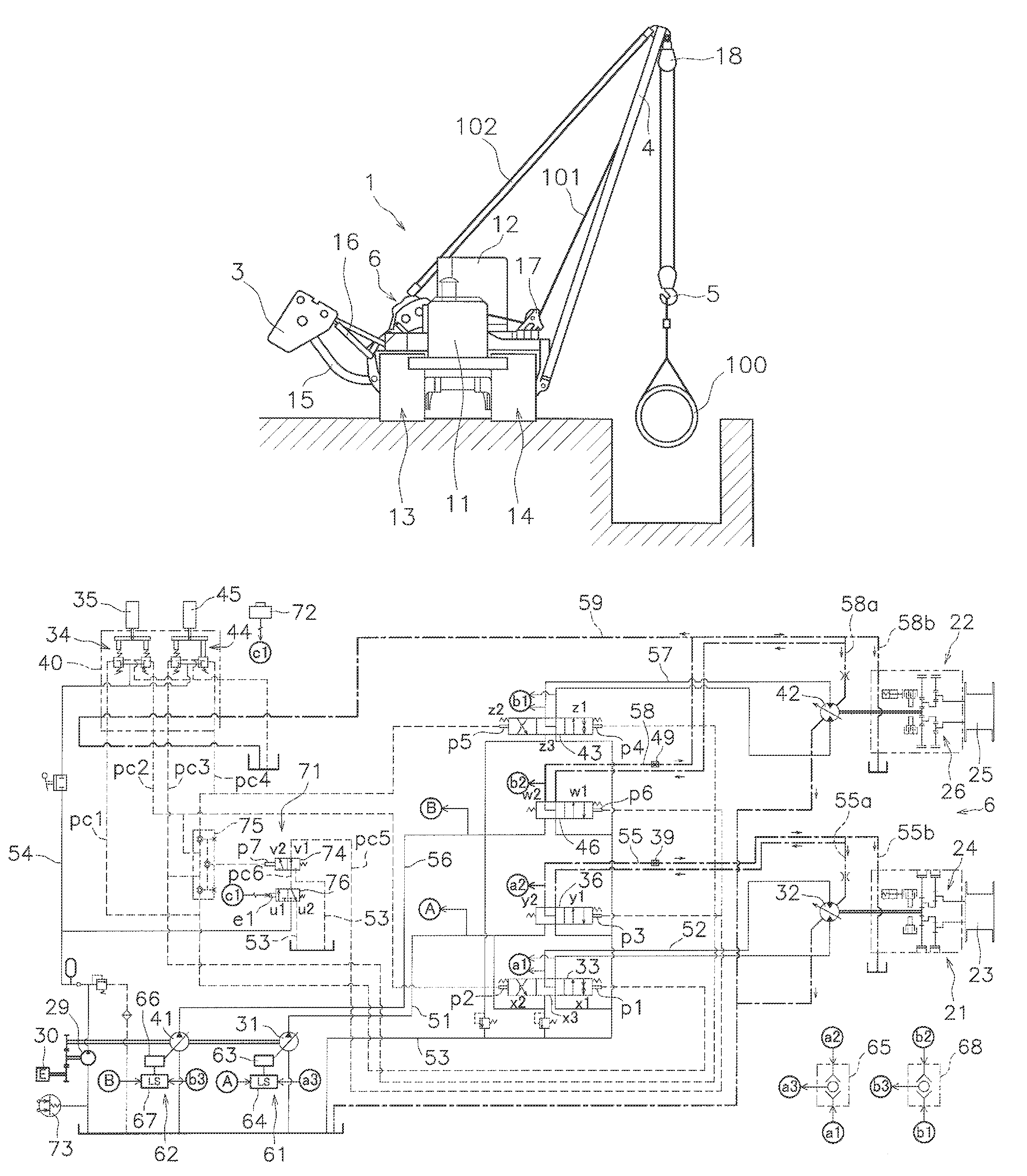
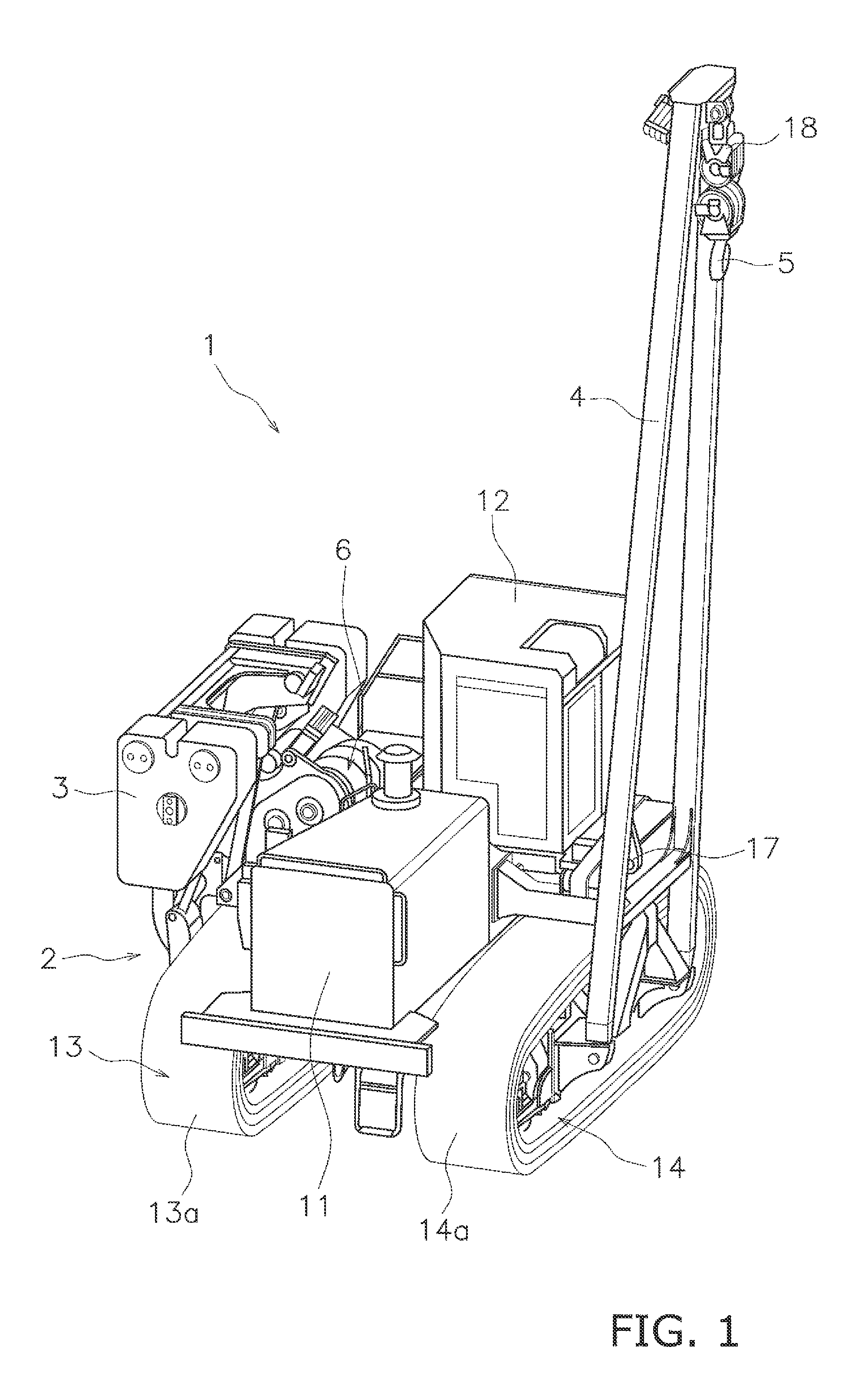
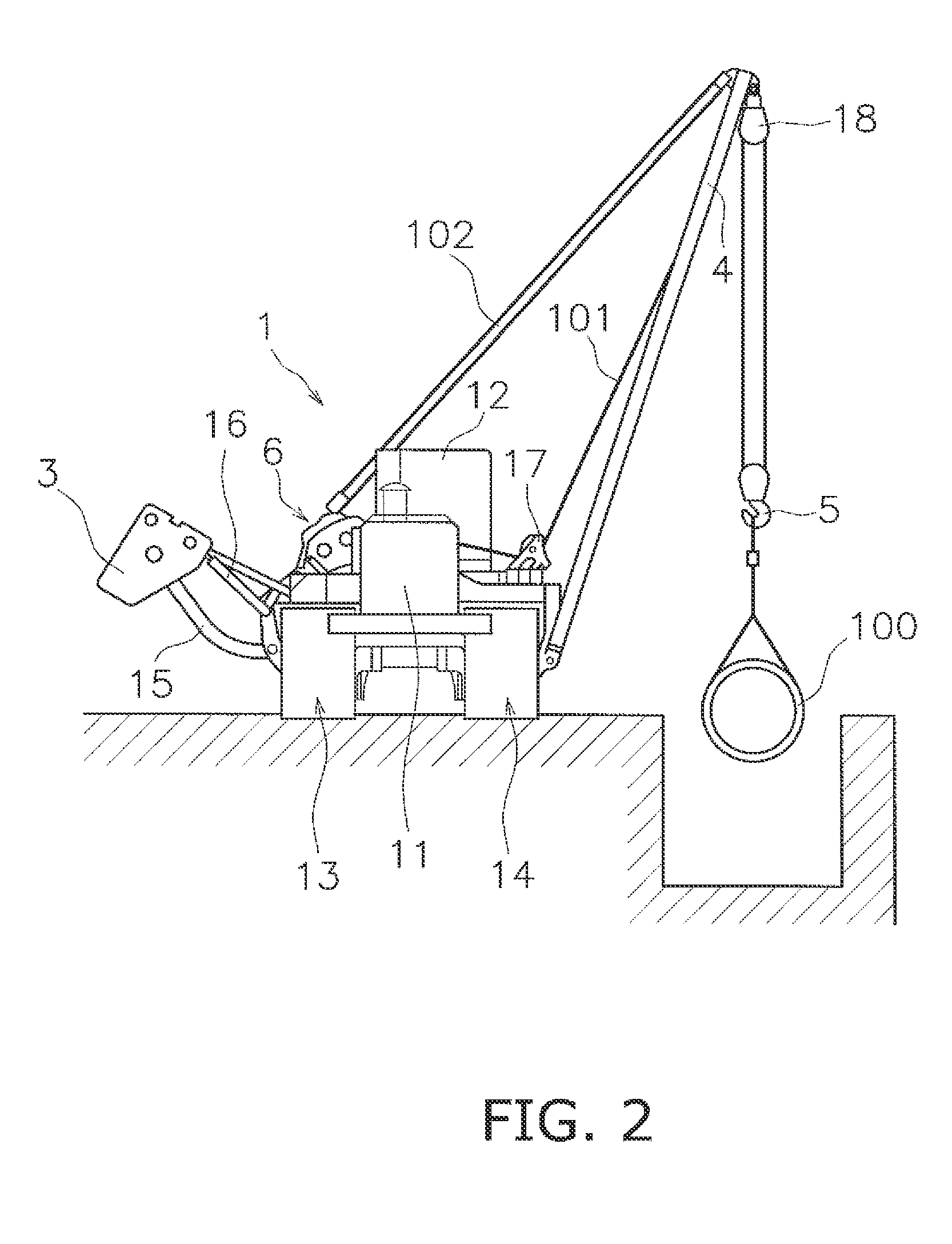
[0021]A pipe layer 1 according to the first embodiment of the present invention is shown in FIG. 1. FIG. 1 is a perspective view showing the appearance of the pipe layer 1. The pipe layer 1 includes a vehicle body 2, a counterweight 3, a boom 4, a hook 5, and a winch device 6. To facilitate understanding of the drawing, a belowmentioned first wire 101 and a second wire 102 are omitted from FIG. 1.

[0022]The vehicle body 2 includes an engine compartment 11, a cab 12, and a pair of travel devices 13 and 14. A belowmentioned engine 30 is disposed in the engine compartment 11. The cab 12 and other devices such as hydraulic pumps 29, 31, 41 (see FIG. 3) are disposed rearward of the engine compartment 11. The travel devices 13 includes crawler belt 13a. The travel devices 14 includes crawler belt 14a. The pipe layer 1 travels due to the crawler belts 13a and 14a being driven by a driving force from the engine 30.

[0023]The counterweight 3 is mounted on one lateral side portion of the vehicl...


PUM


Abstract

A warm-up pilot pressure control unit adjusts pilot pressure inputted to a first flow channel open / close unit so that the flow channel open / close unit is switched to an open state when a warm-up start state is entered under the necessary condition that a first winch operation member is in a neutral position. When the first flow channel open / close unit is in the open state, a first pump displacement adjustment unit adjusts the displacement of a first hydraulic pump so that the differential pressure between a first pump hydraulic circuit and a first warm-up hydraulic circuit becomes constant at a predetermined set pressure.

Description

CROSS-REFERENCE TO RELATED APPLICATIONS[0001]This application claims priority to Japanese Patent Application No. 2010-284641 filed on Dec. 21, 2010, the disclosure of which is hereby incorporated herein by reference in its entirety.TECHNICAL FIELD[0002]The present invention relates to a pipe layer and a warm-up method for a pipe layer.BACKGROUND ART[0003]A pipe layer is a work vehicle used for installing pipes at petroleum and natural gas delivery pipeline construction sites and the like. For example, at a pipeline construction site, multiple pipe layers are lined up in a row and the pipe layers wind up a wire using a winch to lift up the pipes. The winch is coupled with a hydraulic motor and rotated by hydraulic pressure.[0004]A warm-up is performed to raise the temperature of the hydraulic fluid in typical hydraulic driven machines such as hydraulic excavators and the like. The warm-up generates a pressure loss to cause the hydraulic fluid temperature to be raised by causing the h...

Claims


Application Information

Patent Timeline
Patent Type & Authority Patents(United States)
IPC IPC(8): B66D1/44F16L1/028F15B21/04B66C23/44F16D31/00F15B21/0427
CPCB66D1/44F15B21/042Y10S60/905F16L1/028B66C23/44F15B21/0427
Inventor UEMURA, TAKUYATAKEUCHI, YASUHIKONODA, TAKASHI
Owner KOMATSU LTD
Why Eureka
Try Eureka