Breast pump system

a pump system and pump body technology, applied in the field of pump body systems, can solve the problems of difficult for a user to do discretely, difficult to clean, and difficult to isolate, and achieve the effect of reducing the number of problems of system, and reducing the service life of the system

Active Publication Date: 2018-12-20
CHIARO TECH LTD
View PDF18 Cites 44 Cited by
  • Summary
  • Abstract
  • Description
  • Claims
  • Application Information

AI Technical Summary

Problems solved by technology

However, these systems present a number of significant disadvantages.
This is obviously difficult for a user to do discretely, such as in an office setting.
The known devices are also typically noisy, uncomfortable, and hard to clean.
As the collection bag systems are collapsible, it can be difficult for a user to extract all of their milk from the bag, due to the small cut opening that is needed and the capillary action between the bonded plastic sheets that form the bag.
This waste can be disheartening for the user, as this is food for their child.
The bags are also not re-usable, so the user is required to purchase and maintain a stock of these.
As well as presenting a recurring cost, if the user runs out of stock they are unable to use the product until more bags are purchased.
Furthermore, as a result of the collapsible bags, a complex and somewhat noisy pumping arrangement is necessary.
In addition to these systems being particularly complex and wasteful, only a relatively small bag can be used.
However, the design of this breast pump system results in a number of problems.
The use of an annular membrane, with the fluid flow path running through the opening of the annulus is undesirable as it results in a large and bulky device.
However, viewing the milk bottle is not always possible, for example in a breast pump that collects milk while being worn inside a maternity bra.
Particularly at times when liquid enters the container at a high flow rate, this accuracy cannot be guaranteed, leading to significant cumulative errors.
An accurate indication of the level of liquid in the container in this apparatus is also reliant on the sensing mechanism always being on during the pumping process, so that power consumption of the sensing mechanism is correspondingly high.
These systems require the user to remove or unbutton any over-garments, and are uncomfortable when not pumping.
It is not designed to accommodate a breast pump.

Method used


Image

  • Breast pump system
  • Breast pump system
  • Breast pump system

Examples


Embodiment Construction

[0072]We will now describe an implementation of the invention, called the Elvie™ pump, in the following sections:

[0073]Section A: The Elvie™ Breast Pump System

[0074]Section B: An IR System

[0075]Section C: A Bra Clip

[0076]Section D: Piezo Pumps and Wearable Devices

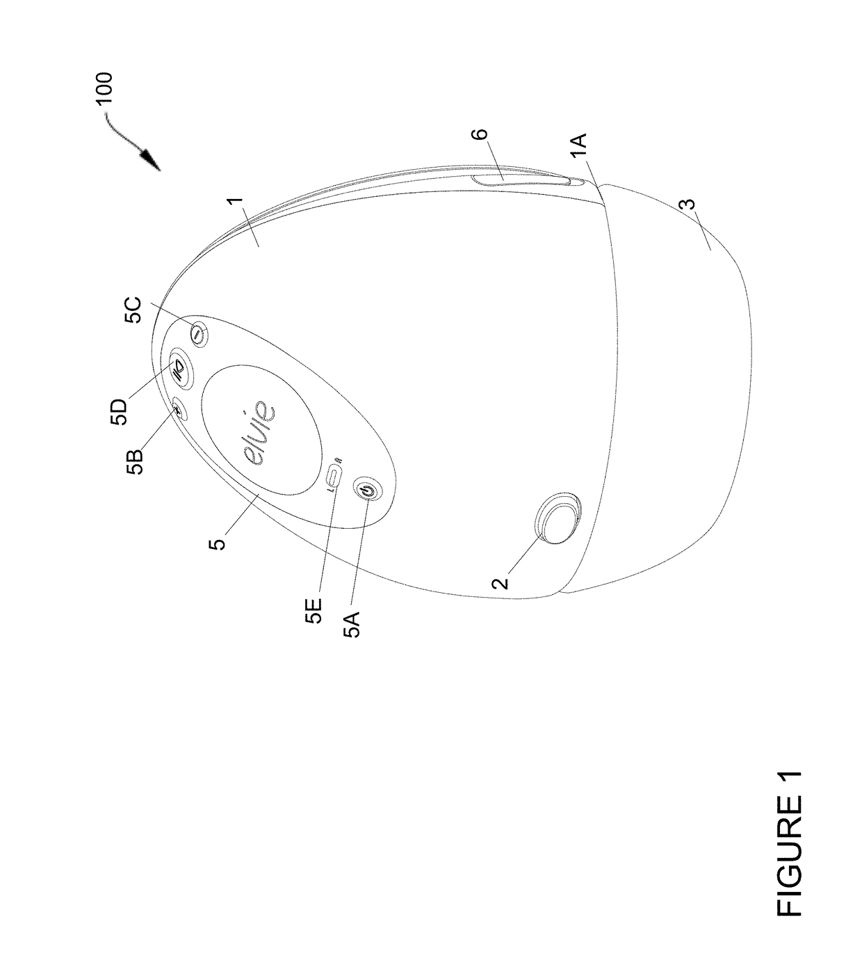
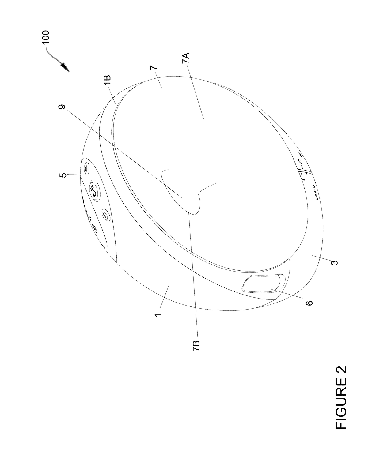
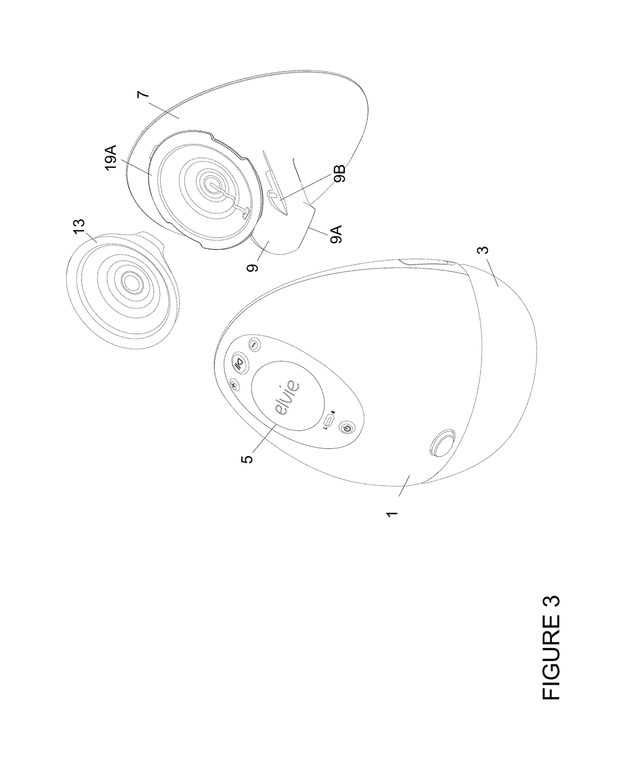
[0077]Section A: The Elvie™ Breast Pump System

[0078]1. Elvie™ Breast Pump System Overview

[0079]An implementation of the invention, called the Elvie™ pump, is a breast pump system that is, at least in part, wearable inside a bra. The breast pump system comprises a breast shield for engagement with the user's breast, a housing for receiving at least a portion of the breast shield and a detachable rigid milk collection container attachable, in use, to a lower face of the housing and connected to the breast shield for collecting milk expressed by the user, with a milk-flow pathway defined from an opening in the breast shield to the milk collection container. The housing inside also includes a pump for generating a negative pres...


PUM


Abstract

The invention is a wearable breast pump system including a housing shaped at least in part to fit inside a bra and a piezo air-pump. The piezo air-pump is fitted in the housing and forms part of a closed loop system that drives a separate, deformable diaphragm to generate negative air pressure. The diaphragm is removably mounted on a breast shield.

Description

CROSS-REFERENCE TO RELATED APPLICATIONS[0001]This application is based on, and claims priority to, GB Application No. 1709561.3, filed Jun. 15, 2017; GB Application No. 1709564.7, filed on Jun. 15, 2017; GB Application No. 1709566.2, filed on Jun. 15, 2017; and GB Application No. 1809036.5, filed on Jun. 1, 2018, the entire contents of each of which being fully incorporated herein by reference.BACKGROUND OF THE INVENTION1. Field of the Invention[0002]The field of the invention relates to a breast pump system; one implementation of the system is a wearable, electrically powered breast pump system for extracting milk from a mother.[0003]A portion of the disclosure of this patent document contains material, which is subject to copyright protection. The copyright owner has no objection to the facsimile reproduction by anyone of the patent document or the patent disclosure, as it appears in the Patent and Trademark Office patent file or records, but otherwise reserves all copyright right...

Claims


Application Information

Patent Timeline
Patent Type & Authority Applications(United States)
IPC IPC(8): A61M1/06G16H40/63
CPCA61M1/062A61M1/066A61M1/06G16H40/63A61M2205/8206A61M2205/7536A61M2205/583A61M2205/582A61M2205/3327A61M2205/3344A61M2205/502A61M2205/3313A61M2205/3389A61M2205/3553A61M2209/088A61M2205/581A61M2205/587A61M2205/6054A61M2205/3584A61M39/223A61M2205/505A61M2205/80A61M2205/702A61M2205/3334A61M2205/52A61M2209/082A61M2205/3606A61J9/00A61M2205/584A61M39/24A61M2205/10A61M2205/07A41C3/04Y02A90/10A61M1/067A61M1/0697A61M1/06935
Inventor O'TOOLE, JONATHANROLLO, ADAMCARR, ANDREW
Owner CHIARO TECH LTD
Why Eureka
Try Eureka