Method and system for mounting an aircraft engine

a technology for aircraft engines and mounting methods, applied in aircraft power plants, power plant construction, power plant types, etc., can solve the problems of reduced fuel efficiency, increased load at take-off rotation,

Active Publication Date: 2018-12-20
GENERAL ELECTRIC CO
View PDF21 Cites 18 Cited by
  • Summary
  • Abstract
  • Description
  • Claims
  • Application Information

AI Technical Summary

Benefits of technology

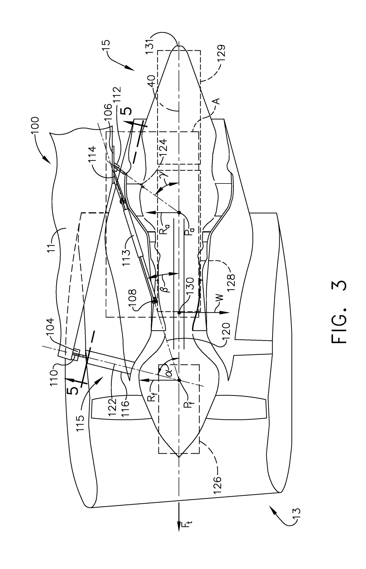
[0008]In yet another aspect, a mounting system for an engine of an aircraft that includes a core engine including a compressor and a low-pressure turbine arranged axisymmetrically about an axis of rotation is provided. The mounting system includes a mounting structure coupled to an exterior of the aircraft and a forward mount interface coupled to the mounting structure forward of the center of gravity of the engine. The forward mount interface is coupled to a fan frame of the engine forming a first angle with respect to the axis of rotation. The mounting system also includes a link mount interface coupl

Problems solved by technology

As engine bypass ratios are increased, the larger fan and increased airflow result in higher loads

Method used


Image

  • Method and system for mounting an aircraft engine
  • Method and system for mounting an aircraft engine
  • Method and system for mounting an aircraft engine

Examples


Embodiment Construction

[0018]In the following specification and the claims, reference will be made to a number of terms, which shall be defined to have the following meanings.

[0019]The singular forms “a,”“an,” and “the” include plural references unless the context clearly dictates otherwise.

[0020]“Optional” or “optionally” means that the subsequently described event or circumstance may or may not occur, and that the description includes instances where the event occurs and instances where it does not.

[0021]Approximating language, as used herein throughout the specification and claims, may be applied to modify any quantitative representation that could permissibly vary without resulting in a change in the basic function to which it is related. Accordingly, a value modified by a term or terms, such as “about,”“approximately,” and “substantially,” are not to be limited to the precise value specified. In at least some instances, the approximating language may correspond to the precision of an instrument for m...


PUM


Abstract

A system for mounting an engine to an aircraft includes an engine forward mount angled toward the forward end of the engine at a first angle. At least two thrust links extend between an engine aft mount to a link support connection at a second angle. The engine aft mount is angled toward the forward end of the engine at a third angle. A projection of a load vector of the engine forward mount onto a vertical plane extending through the axis of rotation of the engine and a projection of a load vector of each of the at least two thrust links onto the vertical plane intersect the axis of rotation of the engine within a first vertical plane segment extending between a forward end of a nose of a fan assembly and forward of a forward mount interface.

Description

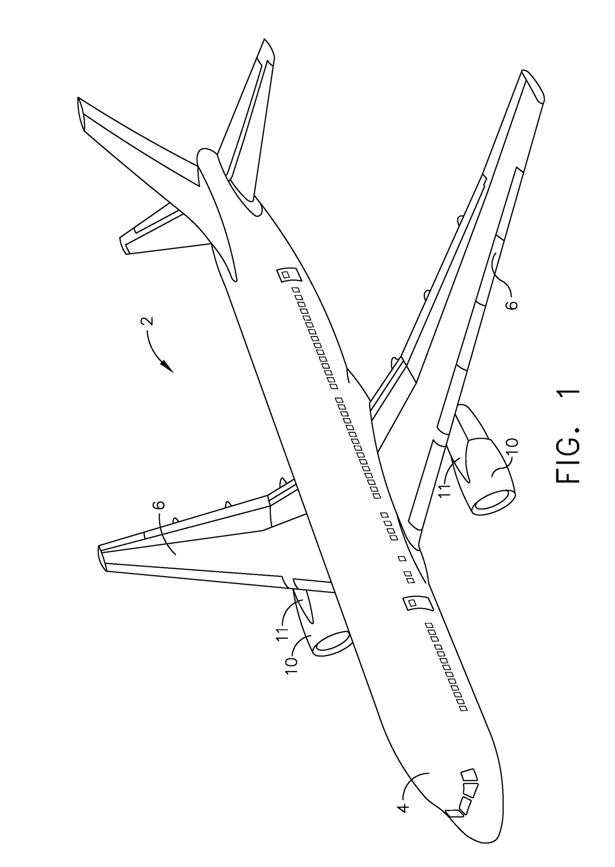
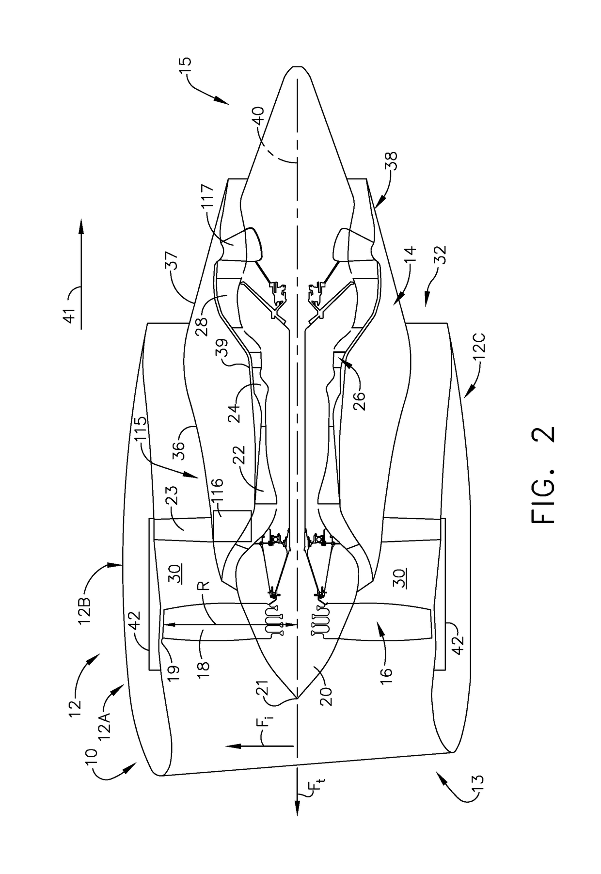
BACKGROUND[0001]The present disclosure generally relates to systems and methods for mounting an aircraft engine to an aircraft. More particularly, this disclosure relates to a mounting system and method adapted to reduce backbone deflection that can occur in an aircraft engine as a result of aerodynamic, gravitational, inertial, and thrust loads during aircraft operation.[0002]At least some known gas turbine engines, such as turbofans, include a fan, a core engine, and a power turbine. The core engine includes at least one compressor, a combustor, and a high-pressure turbine coupled together in a serial flow relationship. More specifically, the compressor and high-pressure turbine are coupled through a shaft to form a high-pressure rotor assembly. Air entering the core engine is mixed with fuel and ignited to form a high energy gas stream. The high energy gas stream flows through the high-pressure turbine to rotatably drive the high-pressure turbine such that the shaft rotatably dri...

Claims


Application Information

Patent Timeline
IPC IPC(8): B64D27/26B64D27/12B64D29/02
CPCB64D27/26B64D2027/262B64D29/02B64D27/12B64F5/10B64D2027/266B64D2027/268
Inventor STUART, ALAN ROYMONIZ, THOMAS ORYCLEMENTS, JEFFREY DONALDROSE, JOSEPH GEORGE
Owner GENERAL ELECTRIC CO
Why Eureka
Try Eureka