Eureka AIR delivers breakthrough ideas for toughest innovation challenges, trusted by R&D personnel around the world.

Flame simulating assembly for simulated fireplaces including a light channeling shield

Active Publication Date: 2018-12-20
LIVING STYLE B V I LTD
View PDF7 Cites 3 Cited by
  • Summary
  • Abstract
  • Description
  • Claims
  • Application Information

AI Technical Summary

Benefits of technology

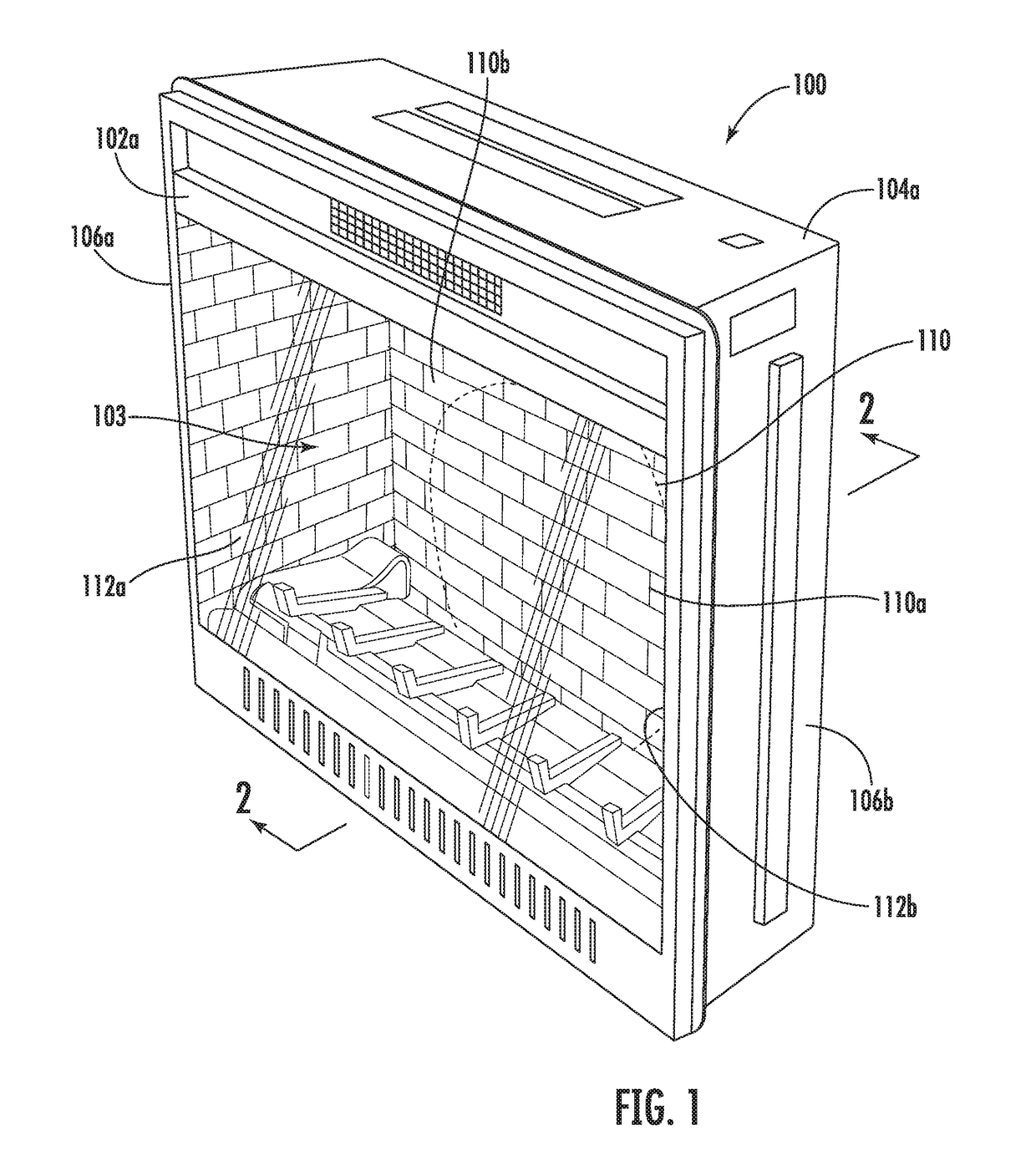
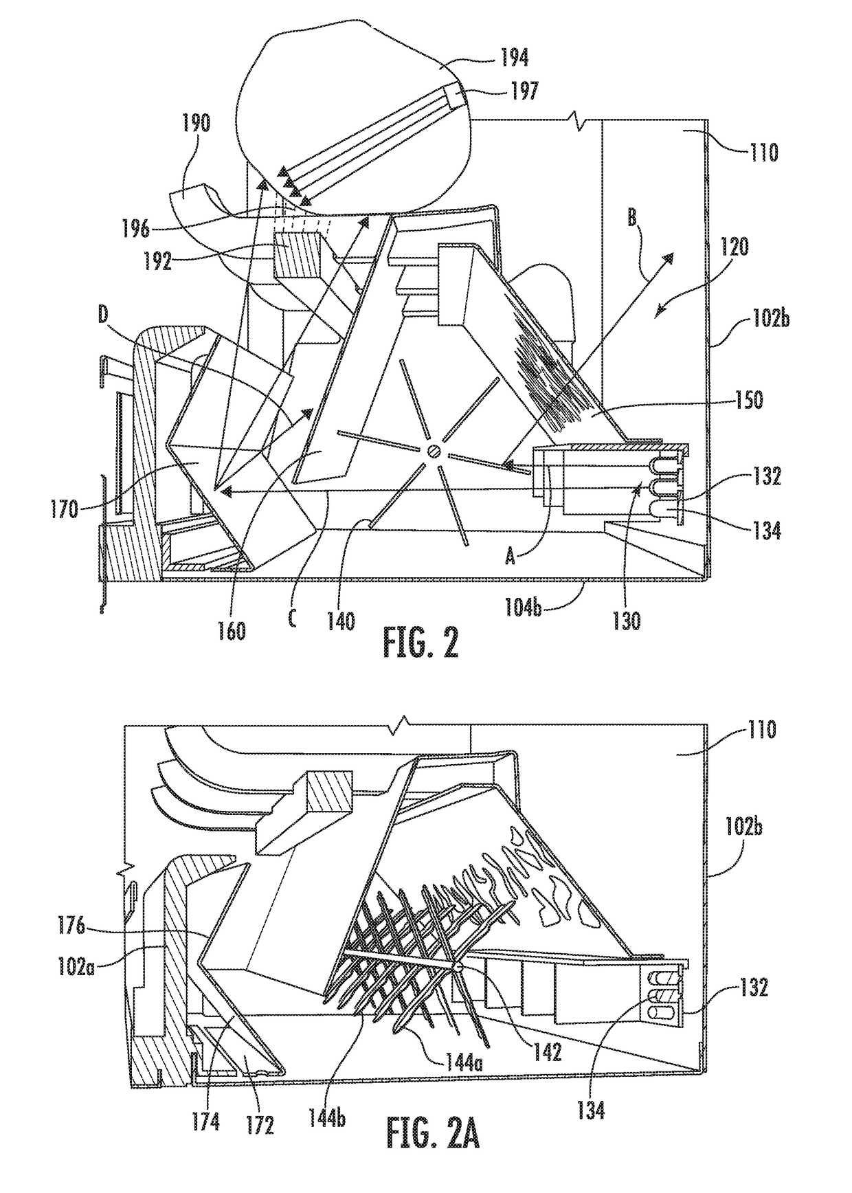
The present patent is for a flame simulating assembly that provides a more realistic flame shape by having non-continuous flame-shaped segments with sharper edges and a wider triangular outline shape. The assembly also includes an integrated ember bed that can be lit from inside and a flame screen that channels light at a desired angle to prevent side spill of light. The design of the assembly is cost-effective, simple, and has improved flame appearance. The technical effects of this patent are better flame shape, improved design, fewer parts, and reduced cost.

Problems solved by technology

However, these false back walls add substantial depth to the devices.
These configurations take up more space, are more costly, and are more fragile in transit.
The simulated fuel bed and logs must be independently lit by a separate light source(s) adding further cost and complexity to the devices.

Method used


Image

  • Flame simulating assembly for simulated fireplaces including a light channeling shield
  • Flame simulating assembly for simulated fireplaces including a light channeling shield
  • Flame simulating assembly for simulated fireplaces including a light channeling shield

Examples


Embodiment Construction

[0040]Certain exemplary embodiments will now be described to provide an overall understanding of the principles of the structure, function, manufacture, and use of the device and methods disclosed herein. One or more examples of these embodiments are illustrated in the accompanying drawings. Those skilled in the art will understand that the devices and methods specifically described herein and illustrated in the accompanying drawings are non-limiting exemplary embodiments and that the scope of the present invention is defined solely by the claims. The features illustrated or described in connection with one exemplary embodiment may be combined with the features of other embodiments. Such modifications and variations are intended to be included within the scope of the present disclosure. Further, in the present disclosure, like-numbered components of the embodiments generally have similar features, and thus within a particular embodiment each feature of each like-numbered component i...


PUM


Abstract

A flame simulating assembly is provided with a reflected flickering light that includes only one light source. Light from the light source passes through a rotating flicker element onto an angled reflector, or mirror, that reflects light up onto a simulated fuel bed and the some of the light is reflected off of the flicker elements towards a flame screen to create a simulated flame. The clipping flicker elements creates a fluttering light effect due to the flicker elements “intermittently dipping” into the light path. This fluctuating light is reflected onto the logs and ember bed in front and creates a dancing effect, which simulates glowing embers.

Description

CROSS-REFERENCE TO RELATED APPLICATIONS[0001]This application is related to and claims benefit of U.S. Provisional Application No. 62 / 522,165 filed Jun. 20, 2017, U.S. Provisional Application No. 62 / 522,170 filed Jun. 20, 2017, U.S. Provisional Application No. 62 / 522,174 filed Jun. 20, 2017, and U.S. Provisional Application No. 62 / 535,938 filed Jul. 23, 2017, the entire contents of which are incorporated herein by reference.BACKGROUND1. Technical Field[0002]The present disclosure relates generally to artificial or simulated fireplaces and stoves, and more particularly to an electronic flame simulating assembly with an enhanced flickering light and modular design.2. Background of the Related Art[0003]In simulated fireplaces, electronic flames or simulated flames are often used to provide the simulated fireplace with a more realistic visual flame or fire effect and also to play a role in decoration. Prior art flame simulation devices may include a light source and rotating reflector w...

Claims


Application Information

Patent Timeline
IPC IPC(8): F21S10/04F24B1/18
CPCF21S10/046F24B1/1808F21V14/06F21Y2115/10F21V11/00F21S10/04F24C7/004F21V14/04F21Y2103/10
Inventor JONES, PAULLASSEN, WILLARDMARSHALL, JR., JOHN R.
Owner LIVING STYLE B V I LTD
Why Eureka
Eureka Blog
Learn More