

System and method for providing uniform illumination as received by an optical detector
- Summary
- Abstract
- Description
- Claims
- Application Information
AI Technical Summary
Benefits of technology
Problems solved by technology
Method used
Image

Examples
Embodiment Construction
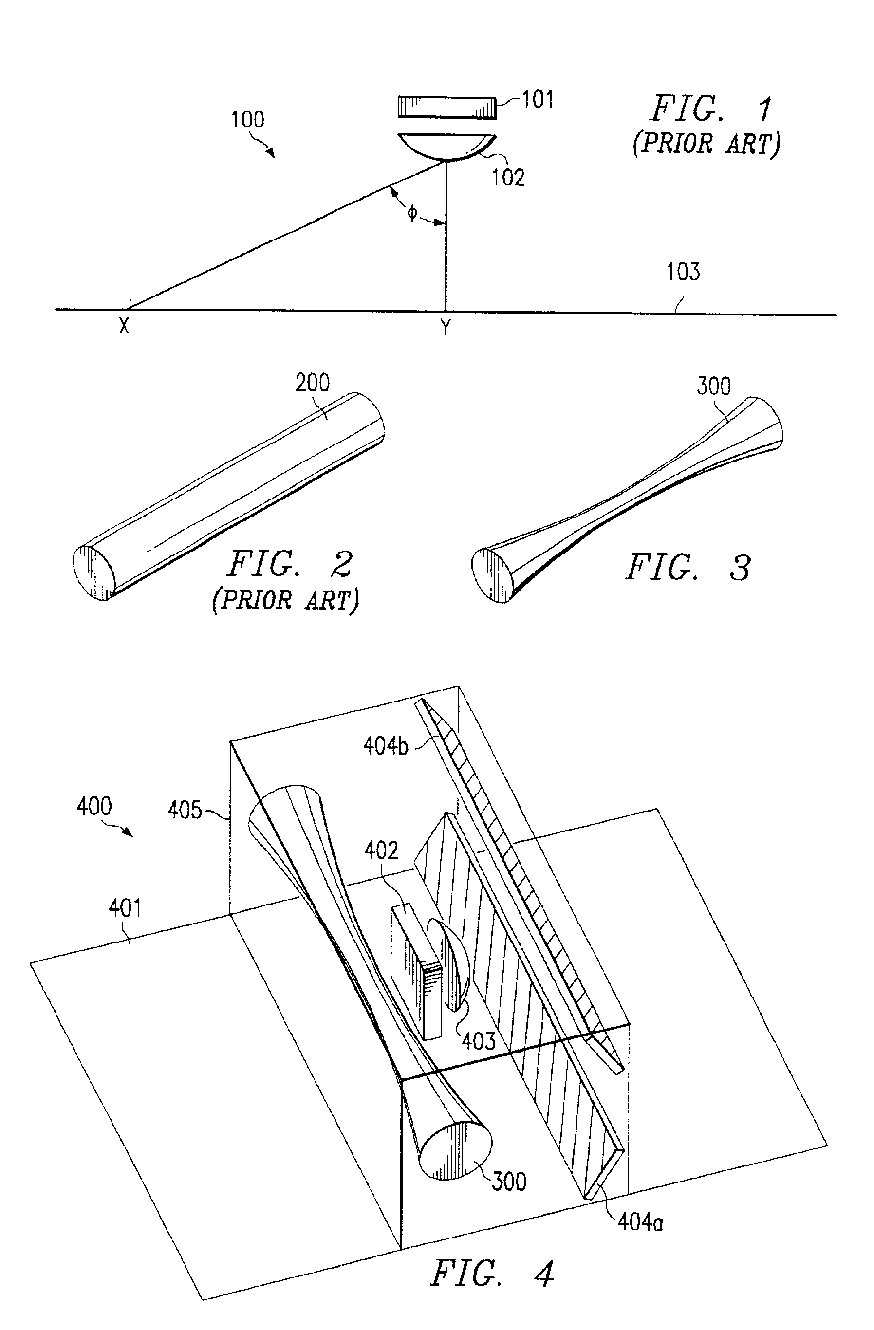
[0020]FIG. 1 depicts a block diagram utilized to illustrate the geometry associated with optical scanners that gives rise to the roll-off effect. System 100 is representative of known scanning applications. System 100 includes optical detector 101. Optical detector 101 captures the image light and digitizes the received image light to construct a digital image of scan line 103. Optical detector is relatively small in comparison to scan line 103. Accordingly, system 100 includes optical component 102 (e.g., a lens) which operates to reduce the image light received from the scan region to be received across the cross-sectional area of optical detector 101. It shall be appreciated that system 100 is represented at a relatively high level. Specifically, the actual geometry of scanning applications is more complicated due to the use of mirrors and other optical components. However, system 100 comprises sufficient detail to convey the optical characteristics of scanning applications.
[0021...
PUM
 Abstract
Description
Claims
Application Information