Wear-Inhibiting Clip for Draper Cleat or Slat of a Crop Harvesting Header

a technology of draper cleat and crop harvesting head, which is applied in the direction of mowers, agricultural tools and machines, etc., can solve the problems of unmodified force and speed, undesirable wear of draper head, and draper wearing at the head, etc., and achieve the effect of sufficient clamping for

Active Publication Date: 2018-12-27
MACDON INDS
View PDF2 Cites 3 Cited by
  • Summary
  • Abstract
  • Description
  • Claims
  • Application Information

AI Technical Summary

Benefits of technology

[0023]In either embodiment, the clip is arranged such that in the installed condition, the legs are biased inwardly towards a shape of an unstressed and uninstalled condition by the stiffness and resiliency of the material, which in turn biases the legs inwards towards the side surfaces of the cleat for biting the teeth into the side surfaces of the cleat. The clip is thus arranged to generate sufficient clamping force without substantial manipulation of the clip from an un

Problems solved by technology

One problem which arises from this combination of lower support track and draper is that of friction at an interface between the cleat, which presents a surface spaced away from an outer surface of the fabric, and the lower support track which is typically stationary relative to the lower run of the draper moving thereover in direct contact with the lower support track

Method used


Image

  • Wear-Inhibiting Clip for Draper Cleat or Slat of a Crop Harvesting Header
  • Wear-Inhibiting Clip for Draper Cleat or Slat of a Crop Harvesting Header
  • Wear-Inhibiting Clip for Draper Cleat or Slat of a Crop Harvesting Header

Examples


Embodiment Construction

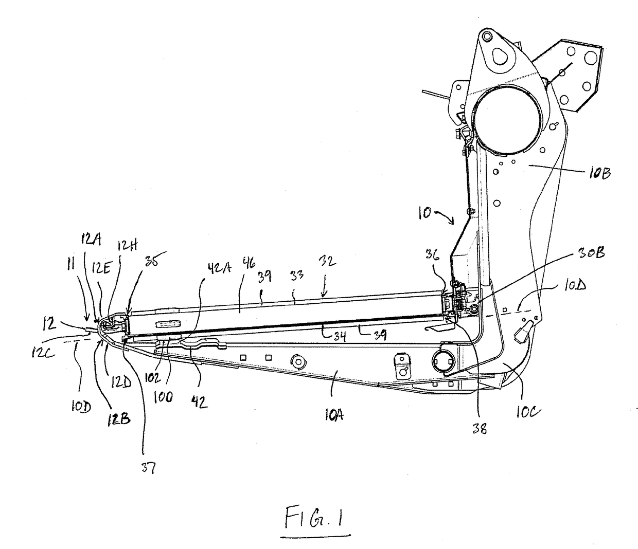
[0071]The following description relates only those parts of the header which are of importance to the present invention and the remaining parts of the header including the frame structure, drives, ground wheels and the like are omitted as these will be well known to one skilled in the art.

[0072]The header therefore comprises a frame 10, one element 10A of which is in the form of a beam extending horizontally and forwardly from a rear support frame structure 10B to a cutter bar assembly generally indicated at 11 for support of that cutter bar assembly across the front of the header. The plurality of beams 10A are arranged at spaced positions along the length of the header frame so as to support the cutter bar assembly 11 as an elongate structure across the front edge of the header. As shown in FIG. 1, the beams 10A are attached rigidly, that is by a rigid connection 10C, to the main rear frame structure 10B to hold the cutter bar 11 in a fixed common plane 10D. That is the rigid conn...


PUM


Abstract

A clip for a draper of a crop header is arranged to cover a portion of a cleat of a draper where the lower run of the draper comes into contact with a lower support track which confines the lower run to a location clear of the cutter bar and a forwardly extending beam of the crop header frame. The clip forms a channel which features teeth presented at an inside of the channel for biting into the cleat so as to retain the clip thereon with the teeth forming ramped surfaces which can slide along the cleat upon installation of the clip, for example by press fitting the clip downwardly onto the cleat.

Description

FIELD OF THE INVENTION[0001]This invention relates to a draper assembly for a crop header and particularly to a device for reducing wear experienced by draper cleats or slats during operation of the draper assembly.BACKGROUND[0002]Draper headers generally include a header frame, an elongate cutter bar along a front edge of the frame including a cutter bar beam which carries a plurality of knife guards for guiding reciprocating movement of a sickle knife across a front edge of the cutter bar. On the header is also mounted a draper assembly including a first and second draper guide roller each arranged at a respective end of the draper assembly spaced apart along the cutter bar with an axis of each roller extending substantially at right angles to the cutter bar, a draper forming a continuous loop of flexible material wrapped around the rollers so as to define a front edge of the draper adjacent the cutter bar, a rear edge of the draper spaced rearwardly of the cutter bar, an upper ru...

Claims


Application Information

Patent Timeline
IPC IPC(8): A01D75/00A01D61/02
CPCA01D75/00A01D34/14A01D61/02A01D41/14B65G15/42
Inventor MARTENS, KRISGEORGISON, RYANROGALSKY, DOUG
Owner MACDON INDS
Why Eureka
Try Eureka