Composite fabrication vent assembly and method

a technology of composite materials and vent assemblies, applied in the field of composite materials fabrication and vent assembly, can solve the problems of compromising the airtight bond required, affecting the quality of the airtight bond, and consuming time and temperamental process of adhesive application, so as to achieve adequate clamping force.

Active Publication Date: 2013-07-11
RUBBERCRAFT OF CALIFORNIA
View PDF10 Cites 11 Cited by
  • Summary
  • Abstract
  • Description
  • Claims
  • Application Information

AI Technical Summary

Benefits of technology

[0019]To counter the effects of heating and cooling on the clamping force between the first and second clamping surfaces due to expansion and contraction of vent assembly components, the vent assembly may include a compression member. The compression member may connect to the carriage member and act on at least one of the body member and the clamping member, to aid in maintaining adequate clamping force between the first and second clamping surfaces when the clamping surfaces are in a relatively closed state, as the vent assembly undergoes variations in pressure and temperature.

Problems solved by technology

However, as discussed below the use of chemical adhesives to create an airtight bond between the bladder material and the vent component presents a number of challenges.
Adhesive bonding is a time consuming and temperamental process.
Improper application of the chemical adhesive can compromise the airtight bond required to be formed between the vent component and the inflatable bladder.
Moreover, if too many air bubbles are present, the bubbles can collectively create a path for unwanted airflow causing a breach in the airtight seal.
As discussed above, the results of the chemical bonding process can be inconsistent leading to failures in the airtight seal between the inflatable bladder and the vent component during testing and prior to use in composite fabrication.
Additionally, the high pressures and high temperatures to which the adhesive bond of the elastomeric tool is exposed during the layup and curing processes during composite fabrication can increase the chance of failures.
At best, a failure of the mold during the composite fabrication process can cause the loss of composite materials, time, revenue, and reputation.
At worst, the improper functioning of the mold due to an undetected failure in the airtight chemical bond between the bladder material and the vent component can lead to structurally deficient components being integrated into a finished product.
The chemical adhesives themselves also represent added inconvenience and expense in terms of their acquisition, storage, handling, and disposal.

Method used


Image

  • Composite fabrication vent assembly and method
  • Composite fabrication vent assembly and method
  • Composite fabrication vent assembly and method

Examples


Embodiment Construction

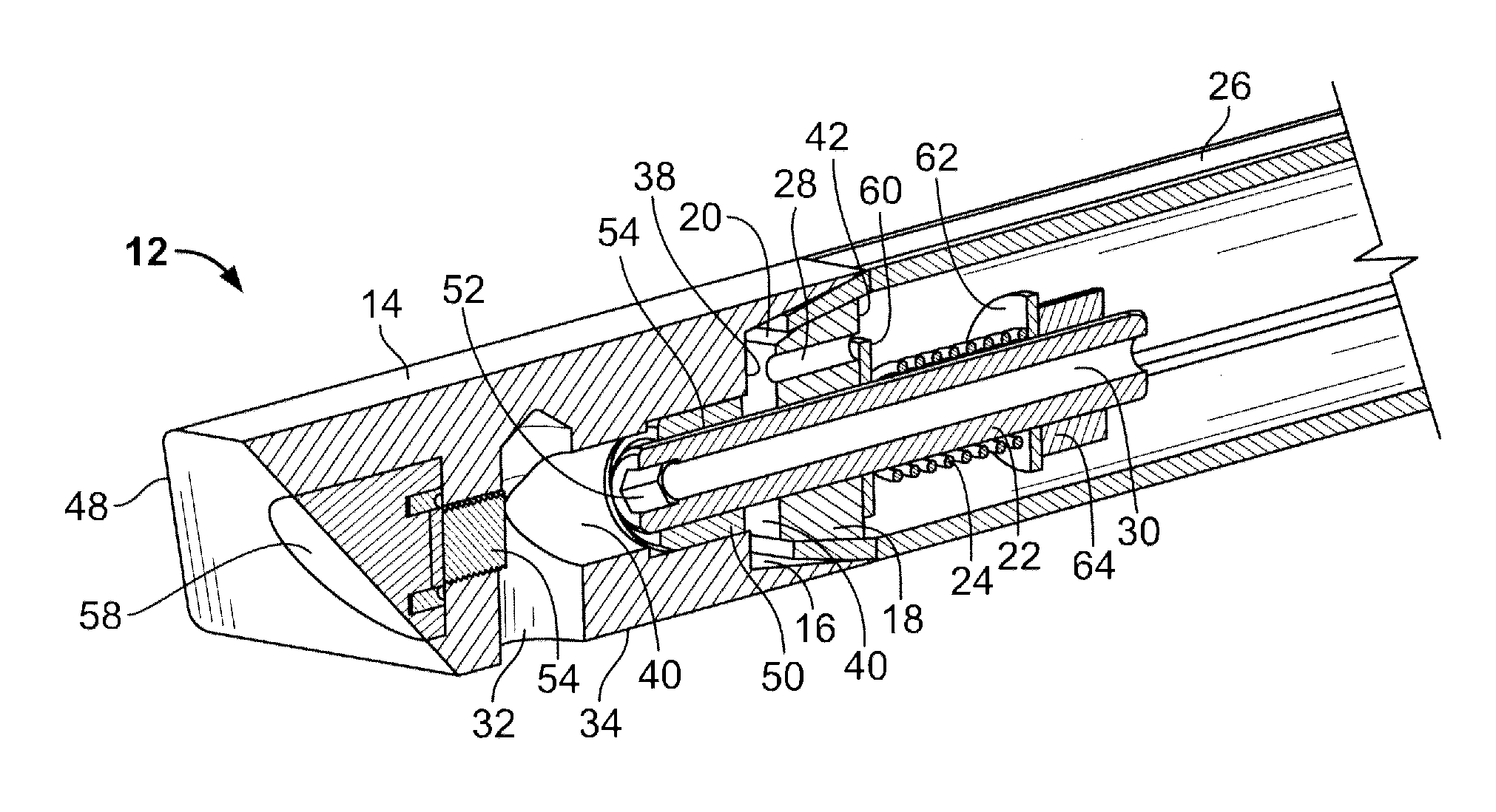
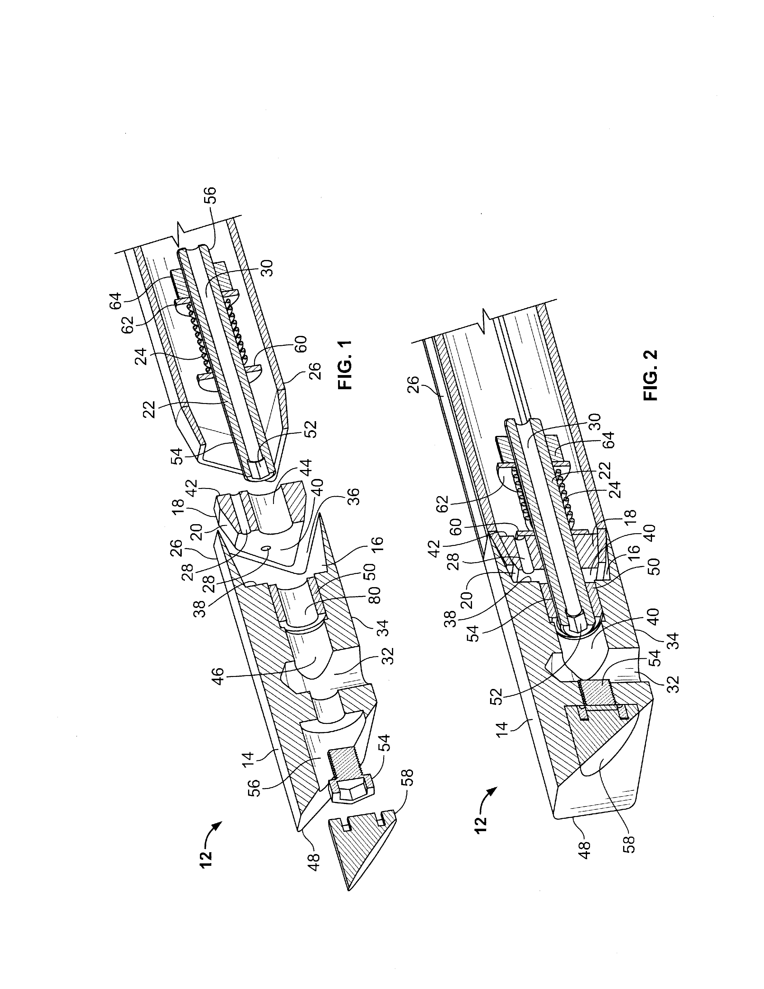
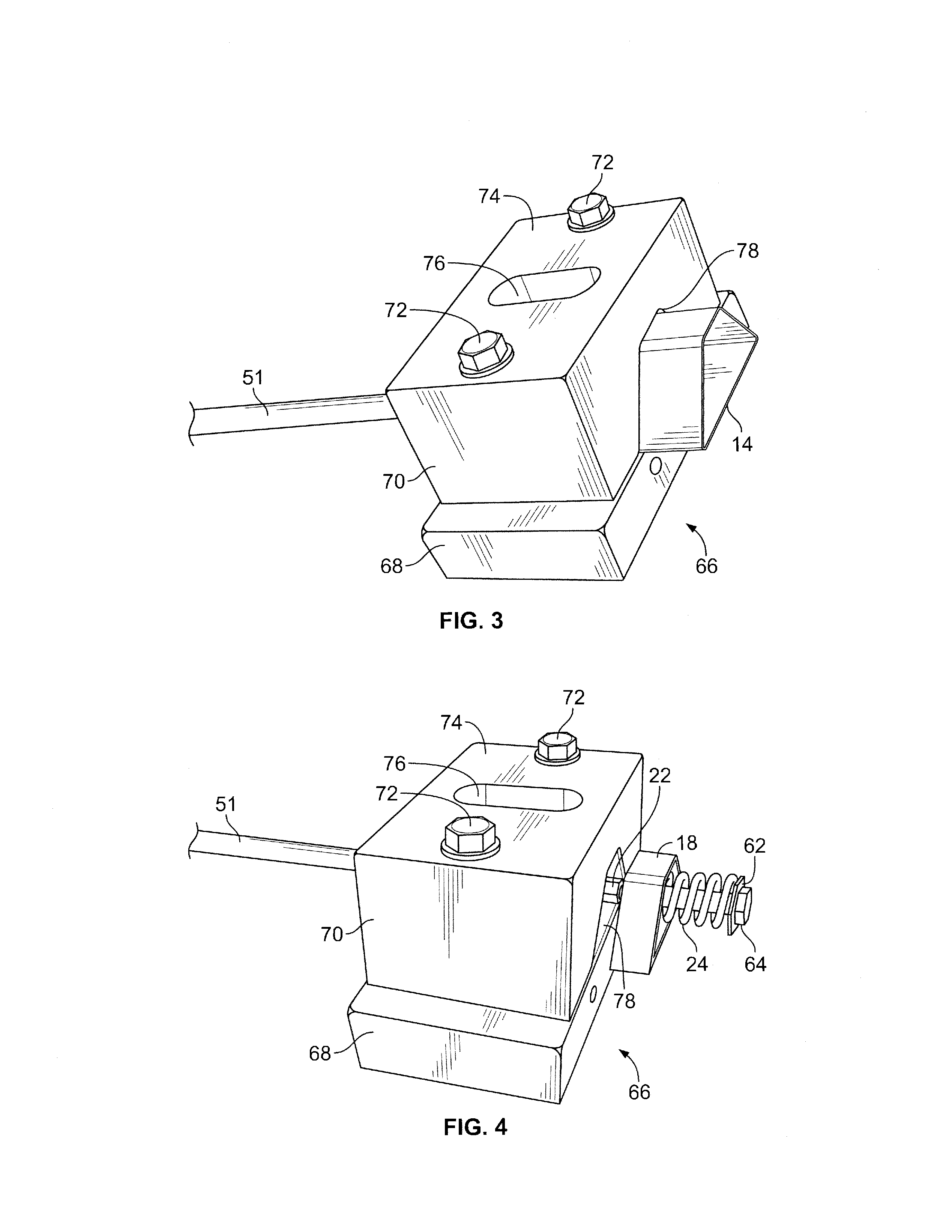
[0031]Referring now to the drawings, and particularly to FIGS. 1 and 2 thereof, a composite fabrication vent assembly 12 in accordance with the present invention is shown. The composite fabrication vent assembly is shown in an unassembled state in FIG. 1. It includes a body member in the form of a vent shell 14 having a first clamping surface 16, a clamping member in the form of a vent plug 18 having a second clamping surface 20, a carriage member in the faun of a pulling or tension rod 22, and a compression member in the form of a compression spring 24. The first and second clamping surfaces have generally concave and convex configurations, respectively. The two clamping surfaces are adapted to receive the open end of an inflatable bladder 26 therebetween when the composite fabrication vent assembly is assembled and in a relatively closed or clamped state, as shown in FIG. 2. The compression spring is adapted to ensure that, when the composition fabrication vent assembly is in the ...


PUM

PropertyMeasurementUnit
rotationaaaaaaaaaa
clamping forceaaaaaaaaaa
clamping surfacesaaaaaaaaaa

Abstract

A composite fabrication vent assembly for connection to an inflatable bladder, the combination of a vent assembly and an inflatable bladder, and a method of mechanically connecting a vent assembly and a bladder. The vent assembly comprises a body member having a first clamping surface, a clamping member having a second clamping surface, and a carriage member interconnecting the body member and the clamping member, with the first and second clamping surfaces in opposing relationship. With the open end of an inflatable bladder inserted between the opposed clamping surfaces, the carriage member is adapted to translate the body member and clamping member toward one another to form an airtight seal with the inflatable bladder. A controlled source of pressurized gas, connected to a gas inlet of the vent assembly, can then inflate and deflate the bladder in a controlled manner through one or more passageways in the vent assembly.

Description

FIELD OF THE INVENTION[0001]This invention pertains generally to tooling apparatus used in the field of composites fabrication and, more particularly, to a vent assembly for coupling to an inflatable mandrel, and related methods.BACKGROUND OF THE INVENTION[0002]Composite materials are generally stronger, lighter and more resistant to high temperatures compared to steel. In general, composite materials also can be more readily formed into irregular shapes and configurations. For these reasons, composite materials are competitive with, if not replacing, steel and other materials in the manufacture of items from tennis racquets, golf clubs, and bicycle frames, to parts for automobiles, aircraft and even spacecraft.[0003]Composite materials are typically made of two general components: a reinforcing material that provides the properties of strength and stiffness, and a binding material or matrix which acts like glue holding the reinforcing material in place. Composite materials have cha...

Claims


Application Information

Patent Timeline
Patent Type & Authority Applications(United States)
IPC IPC(8): B23Q3/00
CPCB29C70/446Y10T29/53796B29C33/10B29C70/54F16L3/10F16L21/08F16B12/10B25B33/00
Inventor HIKEN, ALAN D.LEE, DAVID H.HARSHBERGER, ROBERT L.PHAN, LEO H.SANTOS, RUFINO
Owner RUBBERCRAFT OF CALIFORNIA
Why Eureka
Try Eureka