End surface driving film clamping device

A film and end face technology, applied in the field of hypersonic test equipment, can solve the problem of large radial space of the drive device, and achieve the effect of reducing the occupation of radial space and small volume

Pending Publication Date: 2020-02-11
中国空气动力研究与发展中心超高速空气动力研究所
View PDF0 Cites 11 Cited by
  • Summary
  • Abstract
  • Description
  • Claims
  • Application Information

AI Technical Summary

Problems solved by technology

The thread clamping device has the advantages of a wide range of applicable wind tunnel diameters and a small volume of the clamping device body. However, the driving cylinders of the current thread clamping device are installed on both sides of the rotary nut, driving the rotary nut to rotate tangentially, and driving The radial space occupied by the device is large

Method used


Image

  • End surface driving film clamping device
  • End surface driving film clamping device

Examples


Embodiment 1

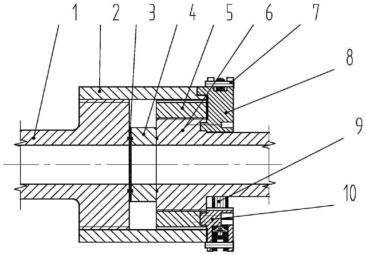
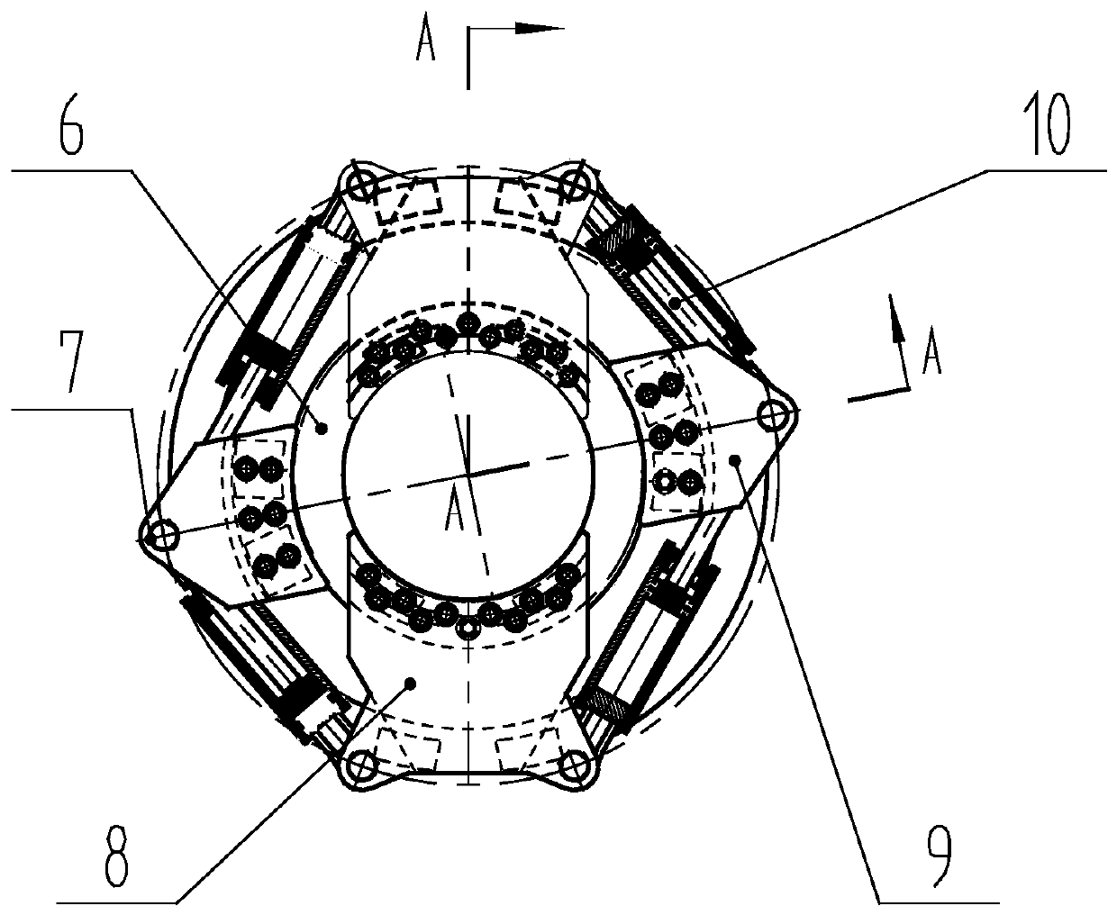
[0032] Such as figure 1 , 2 As shown, the end-face driven clamping device of the present invention includes a driving section 1, a rotary nut 2, a diaphragm 3, a clamping ring 4, a transition nut 5, a driven section 6, a trunnion 7, a double ear support 8, a single ear Support 9 and oil cylinder 10;

[0033] Driving section 1: It is the upstream pipe section of the shock tube, and the inside is a cylindrical cavity. During the test, the cavity is filled with high-pressure driving gas. The right end of the driving section 1 is provided with an external thread, which is threaded with the internal thread on the left side of the rotary nut 2. ;

[0034] Rotary nut 2: connects the upstream pipe section and the downstream pipe section of the shock tube, the two ends of the inner hole are respectively processed with internal threads, the left internal thread is connected with the external thread at the right end of the driving section 1, and the right internal thread is connected w...


PUM


Abstract

The invention discloses an end surface driving film clamping device. A driving section and a rotary nut of the film clamping device are integrated into a whole and serve as a left side section; a filmclamping ring, a transition nut, a driven section, a trunnion, a double-lug support, a single-lug support and an oil cylinder are integrated into a whole and serve as a right side section; a cuttinggroove, with uniform cutting internal threads, of the rotary nut corresponds to a part, in which threads are not removed, of the transition nut with the uniform cutting external threads; and the oil cylinder drives the transition nut to rotate relative to the driven section and the rotary nut, the driven section is driven to move close to the driving section, so that a film and the film clamping ring are clamped. The film clamping ring comprises the trunnion, the double-lug support, the single-lug support and the driving device of the oil cylinder which are all installed in the end surface ofthe rotary nut, and the occupied radial space is reduced. The end surface driving film clamping device can provide enough clamping force for the film of shock tunnel type ground test equipment, and isparticularly suitable for the conditions that the caliber of a shock tube is large, requirement for the clamping force is high, and the space in the circumferential direction is limited.

Description

technical field [0001] The invention belongs to the technical field of hypersonic testing equipment, and in particular relates to an end-face-driven clamping device. Background technique [0002] Pulse-type test equipment such as shock wave wind tunnel is an essential key equipment for ultra-high-speed ground simulation tests. This type of equipment has a common feature: before the test, it is necessary to use a metal diaphragm to divide the shock tube into several pipe sections, and fill different pipe sections with gases of different pressures, and then take measures to rupture the membrane during the test to complete the test. Therefore, it is necessary to design a device between different sections of the shock tube to ensure the clamping and sealing of the diaphragm, which is the clamping device. [0003] The cut thread clamping device and the full thread clamping device are two commonly used thread clamping methods. The clamping principle of the cut-off thread clampin...

Claims


Application Information

Patent Timeline
Patent Type & Authority Applications(China)
IPC IPC(8): G01M9/04
CPCG01M9/04
Inventor 廖振洋钟涌吕治国孔荣宗罗义成李国志
Owner 中国空气动力研究与发展中心超高速空气动力研究所
Why Eureka
Try Eureka