Grooving tool for cutting grooves in workpieces and a grooving tool tool holder for permitting replacement of inserts and permitting inserts to be replaced without moving the tool holder with respect to the grooving tool in which the tool holder is installed

a technology of grooving tool and workpiece, which is applied in the direction of cutting inserts, manufacturing tools, shaping cutters, etc., can solve the problems of cutting off tools being the limiting factor, cutting bodies subject to wear, etc., and achieves good accessibility, sufficient clamping force, and reliable seating of cutting bodies.

Active Publication Date: 2010-06-24
KENNAMETAL INC
View PDF15 Cites 11 Cited by
  • Summary
  • Abstract
  • Description
  • Claims
  • Application Information

AI Technical Summary

Benefits of technology

[0009]An object of the present application is to make possible a simple exchange of a cutting body. Another object of the present application is also to specify a cutting body suitable for this purpose.SUMMARY
[0010]This object is achieved according to the present application by a tool holder. The tool holder has a normally parallelepiped-shaped parent body which extends along a holder longitudinal axis in the x direction. The parent body has a width extending in the y direction and a height extending in the z direction. At its front end, the tool holder comprises a clamping head for accommodating a cutting body. The clamping head has a cutting body receptacle which is defined at the top by a clamping claw and at the bottom by a bottom bearing surface. A cutting body is clamped in place between the clamping claw and the bearing surface. To this end, a separating slot running between the clamping claw and the bearing surface is provided, such that the clamping claw is held elastically on the parent body. For tightening the cutting body in the cutting body receptacle, a tightening element is provided, by means of which the clamping claw can be tightened on the bottom bearing surface. The tightening element extends over the separating slot and is held in an abutment in the parent body, such that, when the tightening element is being tightened, the clamping claw presses directly against the bearing surface. In order to now make possible simple and problem-free accessibility for the exchange of the cutting body, a center axis of the tightening element encloses a tightening angle less than forty-five degrees and in one possible embodiment less than thirty degrees relative to the holder longitudinal axis. The center axis of the tightening element is therefore inclined by the tightening angle within the x-z plane relative to the holder longitudinal axis and thus relative to the x direction, such that, overall, the head surface of a head of the tightening element is oriented very steeply and thus in a readily accessible manner relative to the holder longitudinal axis. Due to the very good accessibility at the front end, an exchange of the cutting body is possible without any problems, even if the tool holder is clamped in place together with a plurality of further tool holders and in a narrow space in a machine mounting. Tests have shown that, on account of the small tightening angle, very good accessibility is provided for and at the same time—despite the small tightening angle—a sufficient clamping force in the normal direction, i.e. essentially in the z direction, can be achieved by means of the tightening element, such that secure and reliable seating of the cutting body in the cutting body receptacle is essentially ensured or promoted. In order to essentially ensure or promote a sufficient clamping force, the clamping angle is in one possible embodiment greater than ten degrees and in one possible embodiment greater than twenty degrees to twenty-five degrees.
[0011]According to one possible embodiment, the clamping claw has a countersunk receptacle for accommodating a head of the tightening element, the countersunk receptacle extending along a center line. This center line is arranged offset relative to the centre axis of the tightening element, to be precise or general offset upward. That is to say, the center axis and the center line have an offset within the x-z plane. Due to this measure, an additional force component is exerted in the clamping direction, i.e. essentially in the z direction, when the tightening element is being tightened. The clamping force is thereby increased. Here, the offset is in one possible embodiment within the range of between 0.2 millimeter and 0.3 millimeter.

Problems solved by technology

On account of the machining, the cutting bodies are subjected to wear and therefore have to be exchanged from time to time.
Such cutting-off tools, in the multiple arrangement of different tools, are normally those which have the greatest length, the “projecting length.” Since the individual cutting edges of the tools have to be set to a common plane, the cutting-off tool is therefore the limiting factor.

Method used


Image

  • Grooving tool for cutting grooves in workpieces and a grooving tool tool holder for permitting replacement of inserts and permitting inserts to be replaced without moving the tool holder with respect to the grooving tool in which the tool holder is installed
  • Grooving tool for cutting grooves in workpieces and a grooving tool tool holder for permitting replacement of inserts and permitting inserts to be replaced without moving the tool holder with respect to the grooving tool in which the tool holder is installed
  • Grooving tool for cutting grooves in workpieces and a grooving tool tool holder for permitting replacement of inserts and permitting inserts to be replaced without moving the tool holder with respect to the grooving tool in which the tool holder is installed

Examples


Embodiment Construction

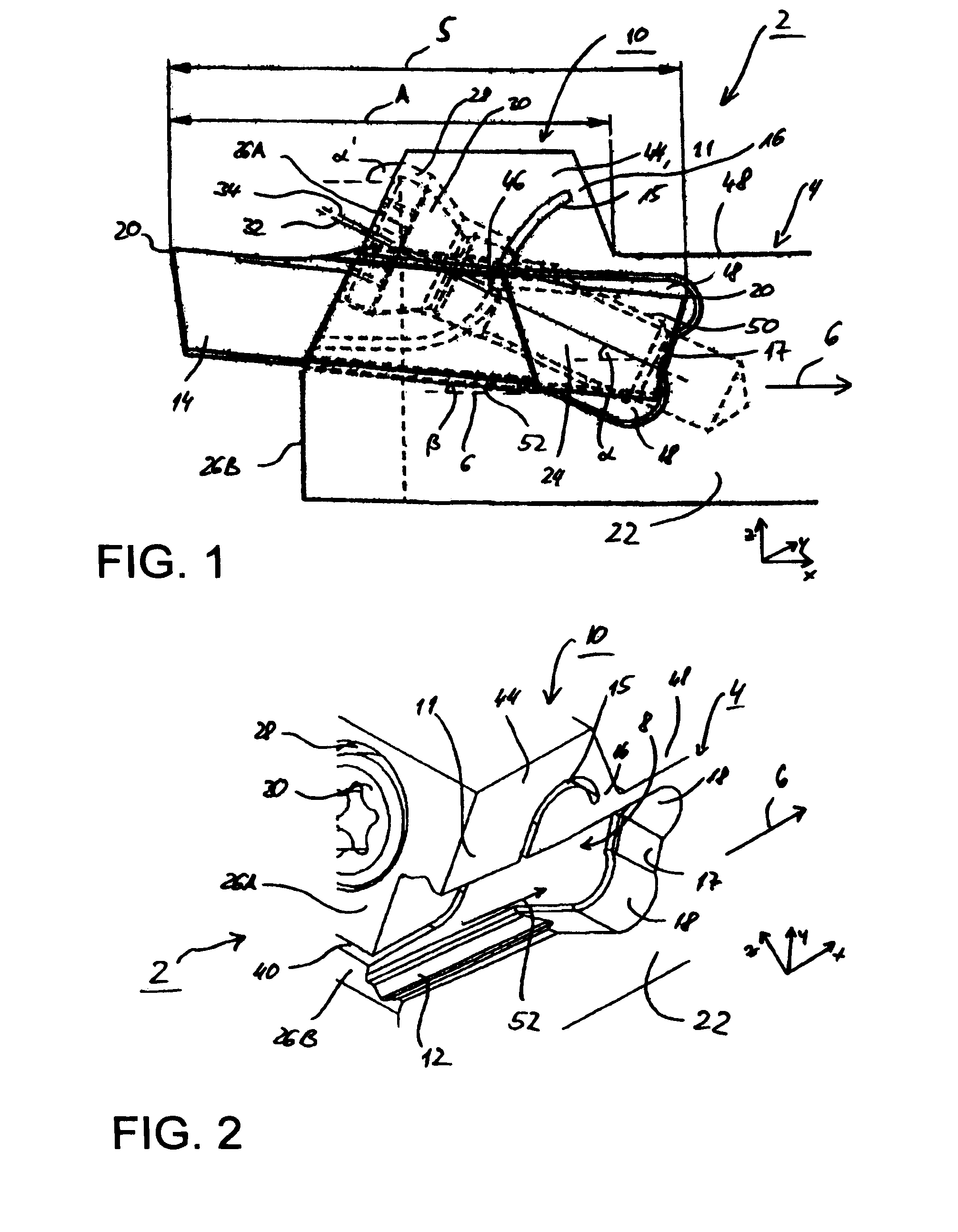
[0042]Parts having the same effect are provided with the same designations in the figures.

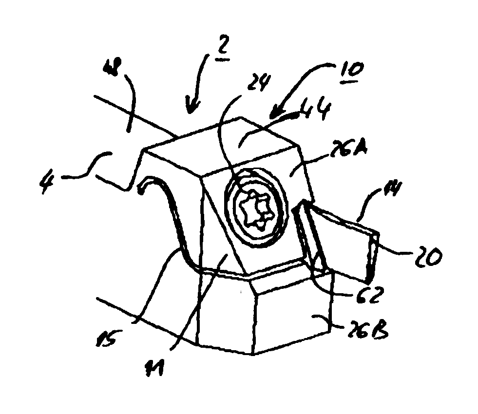
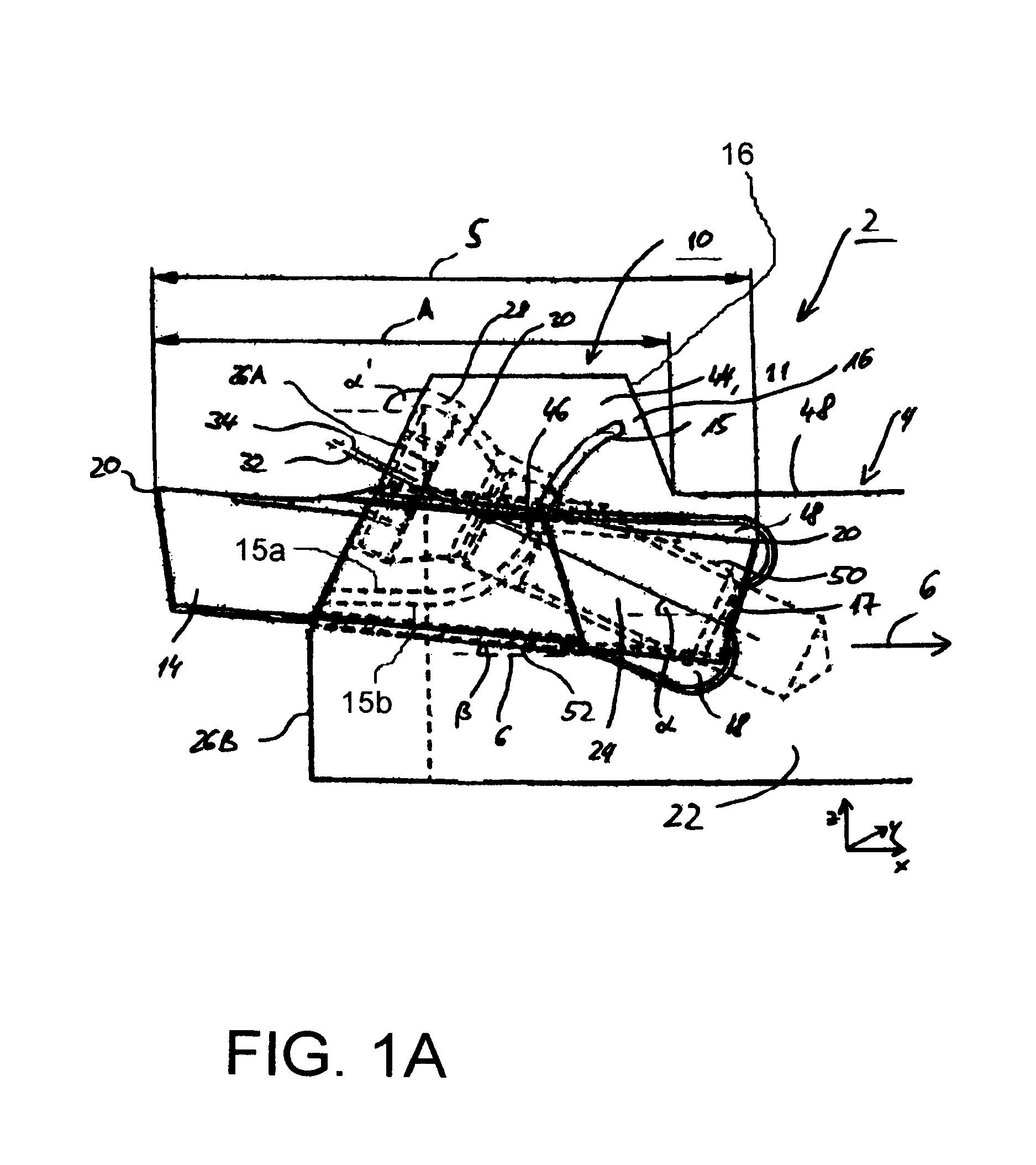
[0043]The tool holder 2 according to FIG. 1 comprises a parent body or connecting body 4 which extends in the direction of a holder longitudinal axis 6. The holder longitudinal axis 6 at the same time forms the x direction of a Cartesian coordinate system. In its height, the parent body 4 extends in the z direction of this Cartesian coordinate system. Its width extends in the x direction of the Cartesian coordinate system. In its front end region, the parent body 4 has a clamping head 10 having a cutting body receptacle 8 (cf. in this respect in FIG. 2). The clamping head 10 comprises at the top essentially a clamping claw or upper portion 11 and at the bottom a bottom bearing surface or lower portion 12. The bottom bearing surface 12 and the underside of the clamping claw 11 have a roof-shaped recess for a cutting body or cutting insert 14 (cf. FIG. 1), said recess forming a guide and said cut...


PUM

PropertyMeasurementUnit
angleaaaaaaaaaa
angleaaaaaaaaaa
acute angleaaaaaaaaaa

Abstract

A grooving tool for cutting grooves in workpieces and a grooving tool tool holder for permitting replacement of inserts and permitting inserts to be replaced without moving the tool holder with respect to the grooving tool in which the tool holder is installed. The abstract of the disclosure is submitted herewith as required by 37 C.F.R. §1.72(b). As stated in 37 C.F.R. §1.72(b): A brief abstract of the technical disclosure in the specification must commence on a separate sheet, preferably following the claims, under the heading “Abstract of the Disclosure.” The purpose of the abstract is to enable the Patent and Trademark Office and the public generally to determine quickly from a cursory inspection the nature and gist of the technical disclosure. The abstract shall not be used for interpreting the scope of the claims. Therefore, any statements made relating to the abstract are not intended to limit the claims in any manner and should not be interpreted as limiting the claims in any manner.

Description

CONTINUING APPLICATION DATA[0001]This application is a Continuation-In-Part application of International Patent Application No. PCT / EP2007 / 008794, filed on Oct. 10, 2007, which claims priority from Federal Republic of Germany Patent Application No. 10 2006 059 717.6, filed on Dec. 18, 2006. International Patent Application No. PCT / EP2007 / 008794 was pending as of the filing date of this application. The United States was an elected state in International Patent Application No. PCT / EP2007 / 008794.BACKGROUND[0002]1. Technical Field[0003]The present application relates to a grooving tool for cutting grooves in workpieces and a grooving tool tool holder for permitting replacement of inserts and permitting inserts to be replaced without moving the tool holder with respect to the grooving tool in which the tool holder is installed.[0004]2. Background Information[0005]Background information is for informational purposes only and does not necessarily admit that subsequently mentioned informat...

Claims


Application Information

Patent Timeline
Patent Type & Authority Applications(United States)
IPC IPC(8): B23B29/12B23B27/16
CPCB23B27/04B23B29/043B23B2205/02B23B2205/045Y10T407/25Y10T407/2288Y10T407/2282Y10T407/23B23B2205/08B23B27/16B23B29/04
Inventor KAUFMANN, IGOR
Owner KENNAMETAL INC
Why Eureka
Try Eureka