Trowel-Grinder-Polisher Machines

Pending Publication Date: 2018-12-27
POWER TROWEL GRINDING IND LLC
View PDF1 Cites 10 Cited by
  • Summary
  • Abstract
  • Description
  • Claims
  • Application Information

AI Technical Summary

Benefits of technology

[0010]Additionally, it is proposed to build remote controlled robotic, walk-behind and sit-on trowel-polisher machines powered from and teetered to the electrical grid by power cord plugged in a wall or ceiling socket and reeled on said machine battery, which can also reel its water hose, supplying water with chemicals from as far as 100 feet. The locomotion of said machine could be wheel driven or hydroplaning gliding and it may be built modular, allowing for quick and easy trowel to polisher switch. Also for

Problems solved by technology

By themselves, each machine is expens

Method used


Image

  • Trowel-Grinder-Polisher Machines
  • Trowel-Grinder-Polisher Machines
  • Trowel-Grinder-Polisher Machines

Examples


Example

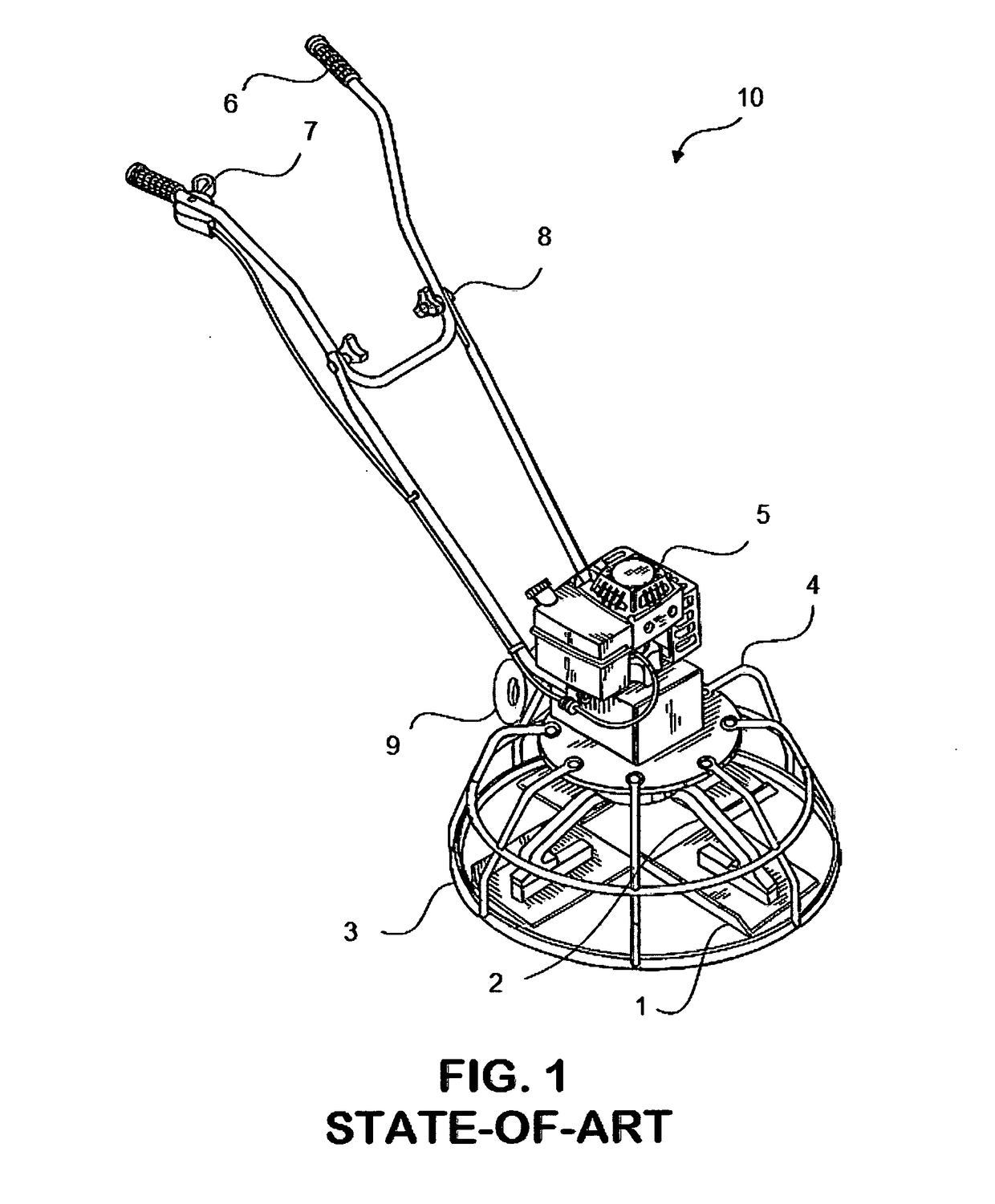
[0076]Attention is now turned to FIG. 1, which illustrates a STATE-OF-THE-ART, walk-behind, concrete polishing power-trowel machine, assembly 10, with four trowel blades, as a chosen example for its simplicity and commonality.

[0077]Machine 10 has four trowel blades 1, rigidly attached to four spider arms 2, a bumper rim 3, a safety cage 4, a powering engine 5, two handles 6, controls 7, optional stash-away hardware 8 and optional stash away roller 9. While blades 1 are shown to be short and wide, they can be long and narrow, as they are in most of the modern power trowels. Engine 5 is shown as a gasoline engine. However, other engines and hybrids, including electrical motors with onboard battery were also proposed before.

[0078]The worker walks behind such a machine with the expectation that his footprint will not show off. With proper timing and care, it does not. That is the state of the art of concrete floor troweling with much sophisticated machines. Some, for instance, have four...


PUM


Abstract

Disclosed is a concrete floor trowel machine of multiple blades with added floor polishing jacket or attachment. It saves expense and time associated with the use of a separate trowel and a polisher in consecutive order, often a day apart. Furthermore, disclosed is a blade replacement polisher disk with metallic hook-and-loop attached steel wool polisher puck, which is the loop component of that means of attachment. Means of slurry feed and suction removal to said puck is also disclosed, whereas said puck may rotate free or by planetary. Said pucks may be attached to blades. Safety cage and slurry splash cover supplement the machine. Removable caster legs are added to ease moving the off-use machine. Disclosed as well are robotic polisher-grinder modules in tandem or in train with changeable trowel-polisher modular inserts with electrical motors and power cable and water hose reels to be serviced from a distance, remotely controlled.

Description

CROSS-REFERENCE TO RELATED APPLICATION[0001]This application claims the benefit of U.S. Provisional Patent Application Ser. No. 61 / 854,424 of Priority Date Apr. 24, 2013 and Ser. No. 61 / 960,457 of Priority Date Sep. 19, 2013 and Ser. No. 62 / 283,765 of Sep. 10, 2015 and Ser. No. 14 / 999,254 of Mar. 28, 2016 and Ser. No. 62 / 499,512 of Priority Date Jan. 28, 2017 and Ser. No. 62 / 605,571 of Priority Date Aug. 16, 2017 which is incorporated here.FIELD OF THE INVENTION[0002]This invention relates to walk-behind or sit-on wet concrete floor trowel machines. Also, to walk-behind or sit-on or non-sitting autonomous dry or wet concrete floor grinding and polishing machines. More specifically, to trowel-to-polisher conversion machines of slurry polishing by soft means on hard backing.BACKGROUND OF THE INVENTION[0003]The invention aims to save on time and cost of machinery used for concrete floor troweling and consecutive polishing, for which tasks, in state-of-the-art and practice, at least two...

Claims


Application Information

Patent Timeline
IPC IPC(8): B24B7/18B24B49/00B24B49/12B24B57/02B24B55/05B24B47/12
CPCB24B7/186B24B49/003B24B49/12B24B57/02B24B55/052B24B47/12B24B27/0076B24D7/066B24D7/10
Inventor CRAFT, CURTISKEMENY, ZOLTAN
Owner POWER TROWEL GRINDING IND LLC
Why Eureka
Try Eureka