Liquid ejection system and computer program

a liquid ejection system and computer program technology, applied in printing and other directions, to achieve the effect of smooth replacement of the main tank

Active Publication Date: 2018-12-27
SEIKO EPSON CORP
View PDF0 Cites 9 Cited by
  • Summary
  • Abstract
  • Description
  • Claims
  • Application Information

AI Technical Summary

Benefits of technology

[0007]According to this aspect, the output control unit causes the display unit to display the refill timing display information regarding a period of time until the refill processing is to be executed, and as a result, a user can recognize the period of time until the refill processing is to be executed in advance.
[0009]According to this aspect, the user can easily confirm the first period in which agitation of the main tank is recommended and the second period in which agitation of the main tank is not recommended by visually recognizing the refill timing display information. Accordingly, the user can visually confirm the period in which agitation of the main tank is recommended.
[0011](4) In the aspect described above, the output control unit, at least at a point in time before the refill processing is to be executed, causes the display unit to display information regarding a liquid remaining amount of the main tank as remaining amount display information, when, with respect to the refill-side sub tank and the main tank that contain the same type of the liquid, the liquid remaining amount of the main tank is less than a liquid consumed amount of the refill-side sub tank when having been functioned as the supply-side sub tank. According to this aspect, the user can prepare a replacement main tank for the main tank whose liquid remaining amount will enter an empty state during execution of the refill processing in advance in response to the remaining amount display information. Accordingly, when the liquid remaining amount of a main tank enters an empty state during execution of the refill processing, the user can smoothly replace the main tank in an empty state with a new main tank.
[0012](5) The aspect described above further includes an audio output unit. The output control unit causes the audio output unit to output information regarding a liquid remaining amount of the main tank as remaining amount audio information, when, with respect to the refill-side sub tank and the main tank that contain the same type of the liquid, the liquid remaining amount of the main tank is less than a liquid consumed amount of the refill-side sub tank when having been functioned as the supply-side sub tank. According to this aspect, the user can prepare a replacement main tank for the main tank whose liquid remaining amount will enter an empty state during execution of the refill processing in advance in response to the remaining amount audio information. Accordingly, when the liquid remaining amount of a main tank enters an empty state during execution of the refill processing, the user can smoothly replace the main tank in an empty state with a new main tank.

Problems solved by technology

The problem described above is not limited to the printing device, and is common among liquid ejection systems that include main tanks that contain various types of liquid, sub tanks that are refilled with the respective types of liquid from the main tanks, and a head that ejects the various types of liquid.

Method used


Image

  • Liquid ejection system and computer program
  • Liquid ejection system and computer program
  • Liquid ejection system and computer program

Examples


embodiment

A. Embodiment

[0027]A-1: Configuration of Liquid Ejection System:

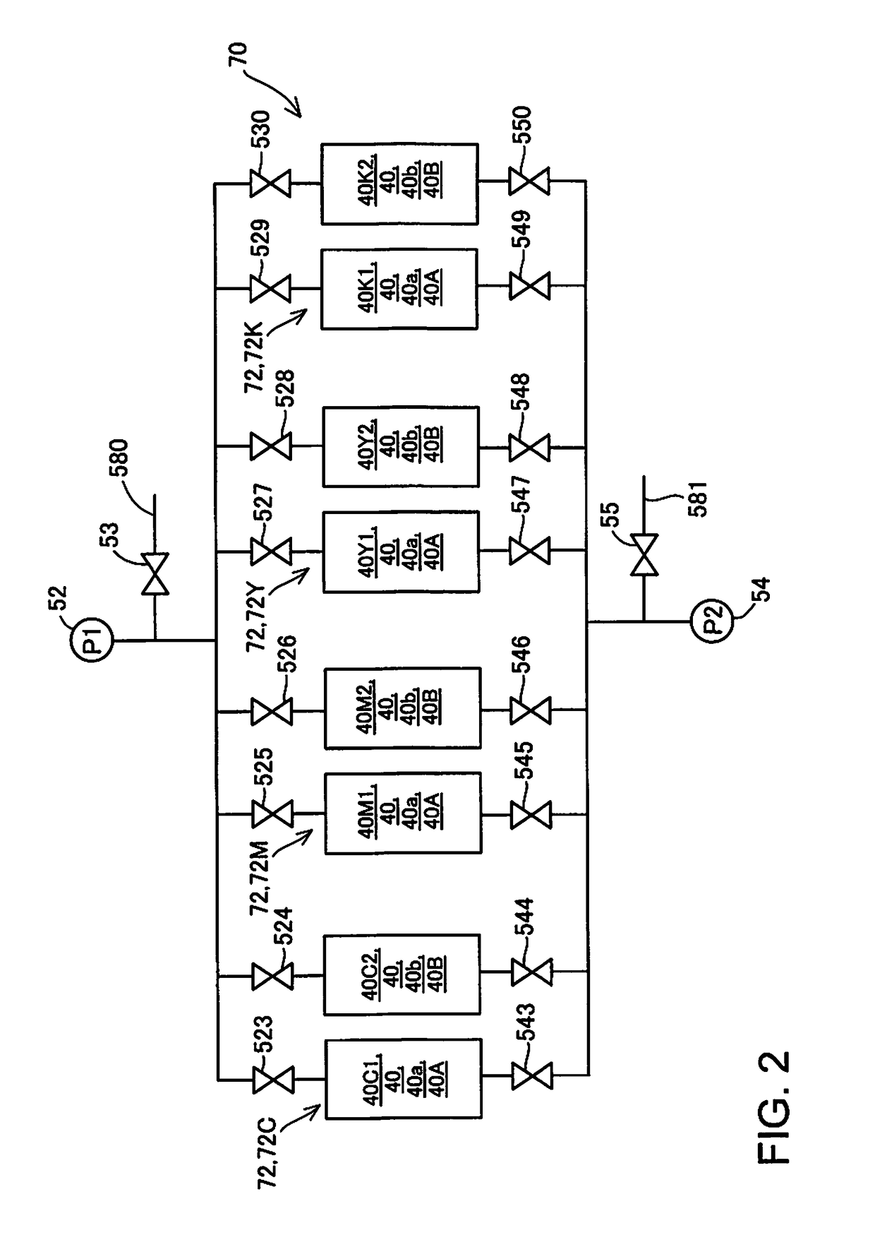
[0028]FIG. 1 is a schematic diagram of a liquid ejection system serving as an embodiment of the invention. FIG. 2 is a diagram for describing a connection state of sub tanks, a supply pump, and a refill pump, and is a control diagram of air pressure.

[0029]A liquid ejection system 10 includes main tanks 20 and a liquid ejection device 30. The main tanks 20 are arranged outside a housing of the liquid ejection device 30. Each main tank 20 can be replaced with a new main tank 20 by a user. When the four main tanks 20 are distinguished therebetween, reference signs “20C”, “20M”, “20Y”, and “20K” are used. The four main tanks 20C to 20K respectively contain (are filled with) liquid of different types. In the present embodiment, yellow (Y) ink, magenta (M) ink, cyan (C) ink, and black (K) ink are respectively contained in the main tanks 20C to 20K, which are different from each other. The main tank 20C contains cyan liquid. T...

first other embodiment

B-1. First Other Embodiment

[0119]In the above-described embodiment, the liquid ejection device 30 includes the display unit 34 and the audio output unit 35 in the liquid ejection system 10, but the function of the display unit 34 or the audio output unit 35 may be included in another apparatus such as a personal computer.

second other embodiment

B-2. Second Other Embodiment

[0120]In the above-described embodiment, the output control unit 322 causes the display unit 34 to display the remaining amount display information Ea and causes the audio output unit 35 to output the remaining amount audio information, but these may be omitted. Also, the output control unit 322 may cause a display portion (display lamp, for example) other than the display unit 34 to display the remaining amount display information Ea. In this case, the user may be notified of the remaining amount display information Ea by lighting or blinking of the display lamp.


PUM


Abstract

Provided is a technique that enables a user to confirm the period of time until refilling of the sub tank with liquid is to be started. A refill control unit 321, when a condition in which a minimum value of suppliable times C of respective plurality (colors) of supply-side sub tanks 40B is less than or equal to a maximum value of full refill refilling times Y of respective plurality (colors) of refill-side sub tanks 40A, the refill processing is performed on the plurality of refill-side sub tanks 40A, and an output control unit 322 causes a display unit 34 to display refill timing display information regarding a period of time until the refill processing will be executed, at least at a point in time before the refill processing is to be executed.

Description

BACKGROUND1. Technical Field[0001]The present invention relates to techniques of liquid ejection systems.2. Related Art[0002]Heretofore, a technique of a printing device is known that includes a first ink tank that contains ink to be supplied to a head, a second ink tank that is connected to the first ink tank, and an ink bottle for refilling the second ink tank with ink (JP-A-2010-201810, for example).[0003]In the known technique, when the amount of ink inside the second ink tank reaches a refilling start amount, the second ink tank is refilled with the ink inside the ink bottle. However, in the known technique, a user desires to know in advance the period of time until the refilling of ink will be started.[0004]The problem described above is not limited to the printing device, and is common among liquid ejection systems that include main tanks that contain various types of liquid, sub tanks that are refilled with the respective types of liquid from the main tanks, and a head that ...

Claims


Application Information

Patent Timeline
Patent Type & Authority Applications(United States)
IPC IPC(8): B41J2/175B41J2/195
CPCB41J2/17506B41J2/195B41J2/17596B41J2/17556B41J2002/17516B41J2/17566B41J2/17509B41J2/175B41J2/17513
Inventor KOGANEHIRA, SHUICHI
Owner SEIKO EPSON CORP
Why Eureka
Try Eureka