Bumper reinforcement and method of manufacturing bumper reinforcement

a technology of bumper reinforcement and manufacturing method, which is applied in the direction of bumpers, vehicle components, vehicular safety arrangements, etc., can solve the problems of high manufacturing cost, complicated manufacturing process of bumper reinforcement, and difficult to bring into surface contact with each other, and achieve the effect of easy surface conta

Active Publication Date: 2018-12-27
AISIN SEIKI KK +2
View PDF8 Cites 3 Cited by
  • Summary
  • Abstract
  • Description
  • Claims
  • Application Information

AI Technical Summary

Benefits of technology

[0018]In general, when a metal material is bent, it is difficult to set a curvature radius of a bent portion to “0.” In the above-described aspect of the disclosure, a part (particularly, its base end) located in front of the cut portion of the intermediate formed body is bent such that the bent part is curved. As illustrated in FIG. 11, a front side part of the inner peripheral part of the cut portion may obliquely intersect with a rear side part of the inner peripheral part of the cut portion, the front side part being located on the side of the front wall, and the rear side part being located on the side of the rear wall. In this case, it is dif

Problems solved by technology

In JP 2015-58759 A, the heating step is necessary, and therefore, a manufacturing process for the bumper reinforcement is complicated and the manufacturing cost thereof is high.
Accordingly, a manufacturing process for the bumper reinforcement is complicated and the manufacture cost thereof is high.
Thus, the number of components is large and the component cost is high, as compared to the bumper reinforcement in JP 2015-58759 A.
Accordingly, even if a tool and a fast

Method used


Image

  • Bumper reinforcement and method of manufacturing bumper reinforcement
  • Bumper reinforcement and method of manufacturing bumper reinforcement
  • Bumper reinforcement and method of manufacturing bumper reinforcement

Examples


Embodiment Construction

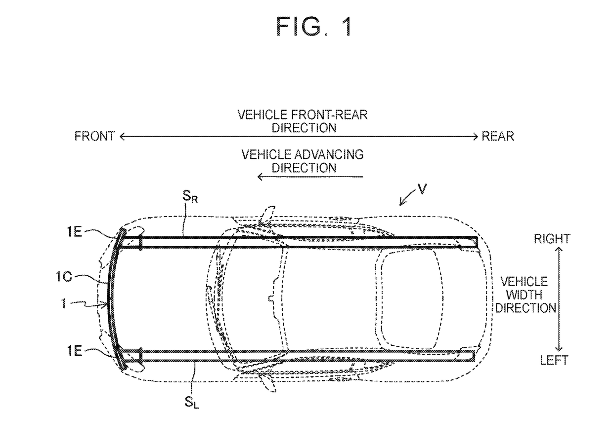
[0032]A bumper reinforcement 1 according to an embodiment of the disclosure is described. First, a structure of a vehicle V to which the bumper reinforcement 1 is applied is described. As illustrated in FIG. 1, the vehicle V includes a pair of right and left side members SR, SL, and the bumper reinforcement 1.

[0033]The side members SR, SL are disposed at an interval in a vehicle width direction. Each of the side members SR, SL extends in a vehicle front-rear direction. Plate-shaped flange portions are respectively provided in front end portions of the side members SR, SL. The bumper reinforcement 1 is fastened to the flange portions.

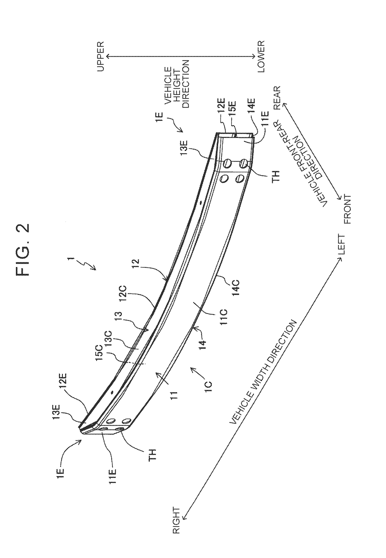
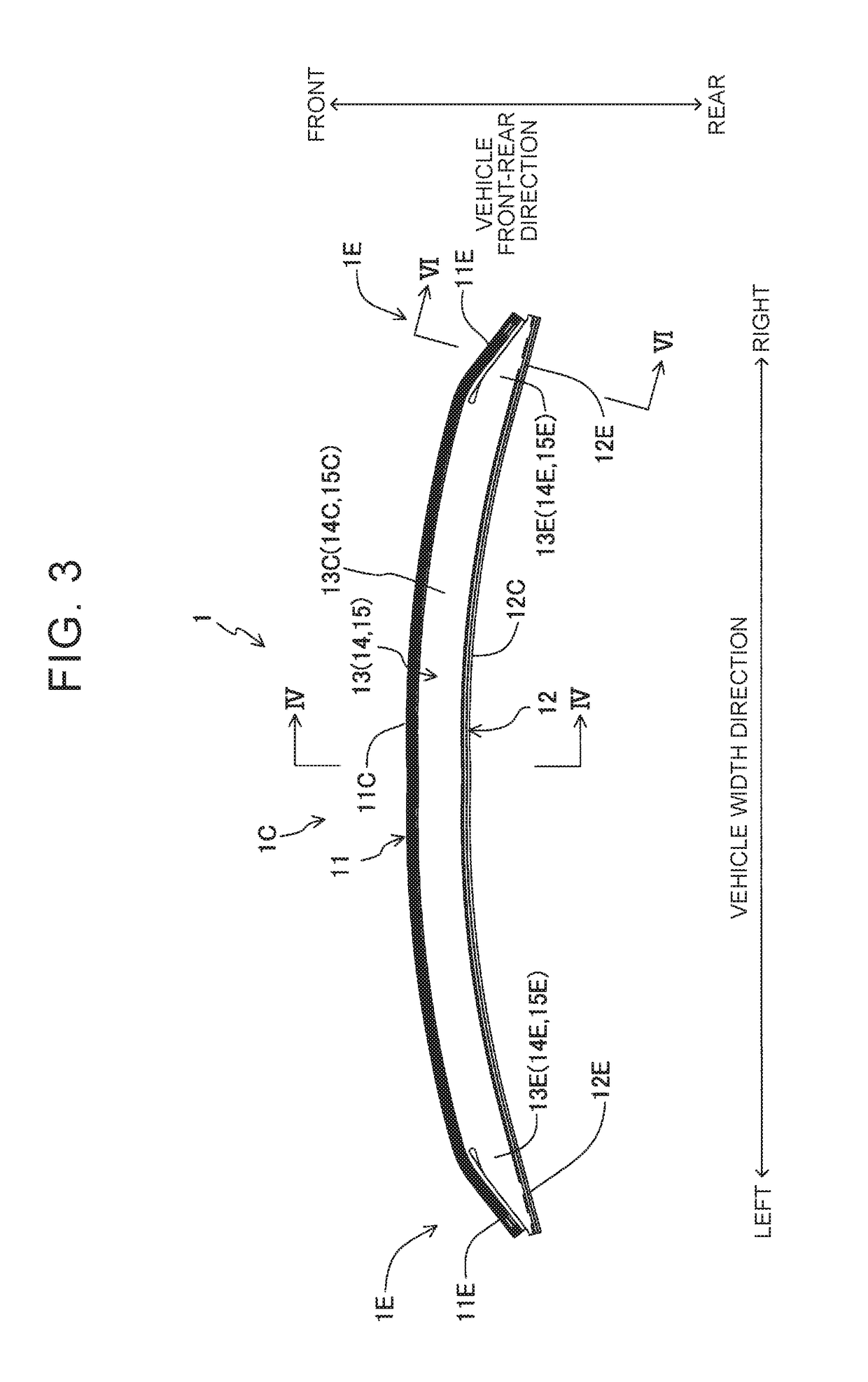
[0034]Next, a structure of the bumper reinforcement 1 is described. As illustrated in FIG. 1, the bumper reinforcement 1 has a polygonal tubular shape (rectangular tubular shape in the embodiment) that extends horizontally from a first end (the right end) of the vehicle to a second end (the left end) of the vehicle in the vehicle width direction. That is...


PUM


Abstract

A bumper reinforcement includes a front wall, a rear wall, and a connection wall. Intermediate portions, in an extending direction, of the front wall and the rear wall are parallel to each other. An end portion, in the extending direction, of the front wall is bent toward the rear wall when viewed from the intermediate portion of the front wall. An end portion, in the extending direction, of the connection wall includes a front part and a rear part, and each of the front and rear parts extends from an inside to an outside in the vehicle width direction. A distance between a front end of the rear part and the rear wall gradually decreases in a direction from a base end of the rear part toward a distal end thereof. The front part is provided so as to extend along the front end of the rear part.

Description

INCORPORATION BY REFERENCE[0001]The disclosure of Japanese Patent Application No. 2017-121083 filed on Jun. 21, 2017 including the specification, drawings and abstract is incorporated herein by reference in its entirety.BACKGROUND1. Technical Field[0002]The disclosure relates to a bumper reinforcement for a vehicle and a method of manufacturing the same.2. Description of Related Art[0003]As described in Japanese Unexamined Patent Application Publication No. 2015-58759 (JP 2015-58759 A), a bumper reinforcement provided in a front end portion of a vehicle has been known. The bumper reinforcement has a rectangular tubular shape extending in a vehicle width direction. That is, the bumper reinforcement is a tubular body surrounded by a front wall, a rear wall, an upper wall, and a lower wall. Note that a rib parallel to the upper wall and the lower wall is provided inside the bumper reinforcement. Further, the length, in a width direction (a direction perpendicular to the front wall or t...

Claims


Application Information

Patent Timeline
IPC IPC(8): B60R19/18B60R19/02B21D53/88
CPCB60R19/18B60R19/023B21D53/88B60R19/04B60R2019/182
Inventor SHIBATA, SHUNJIKITA, KIYOICHISHOBO, JUNMATSUI, KYOSUKEOBAYASHI, TAMAKITAKANAMI, YUTASHIBATA, HIROFUMISAEKI, KOJI
Owner AISIN SEIKI KK
Why Eureka
Try Eureka