
Screw expander

Active Publication Date: 2018-12-27
FUSHENG IND CO LTD
View PDF4 Cites 0 Cited by
  • Summary
  • Abstract
  • Description
  • Claims
  • Application Information

AI Technical Summary

Benefits of technology

The invention is a screw expander that includes a control module to adjust the pressure of the air exhaust from the expansion screw. This is accomplished by changing the coverage rate of the adjusting component covering either the air inlet end or the air outlet end, which in turn changes the opening area of the air outlet end. The adjusted pressure of the air exhaust is then balanced with the low pressure region, reducing power consumption.

Problems solved by technology

In general, the greater the differences between the pressure of an air outlet end of the screw expander and the pressure of an exhausted air reaching the low pressure region are, the greater the power consumption is.
Therefore, how to effectively control the pressure of the air outlet end of the screw expander to be consistent with the pressure of the low pressure region has become an important issue of designing the screw expander.

Method used


Image

  • Screw expander
  • Screw expander
  • Screw expander

Examples


Embodiment Construction

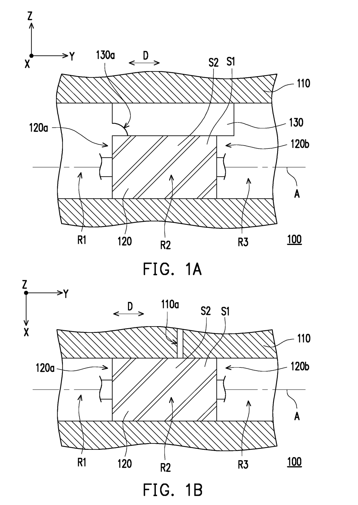
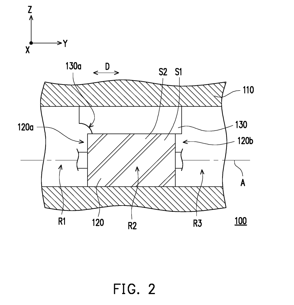
[0026]FIG. 1A is a schematic view of some of components of a screw expander according to an embodiment of the invention. Please refer to FIG. 1A. A screw expander 100 of the embodiment includes a main body 110 and at least an expansion screw 120. The main body 110 has a high pressure region R1, an expansion region R2, and a low pressure region R3. The expansion screw 120 is disposed at the expansion region R2 and has an air inlet end 120a and an air outlet end 120b. The air inlet end 120a is connected to the high pressure region R1. The air outlet end 120b is connected to the low pressure region R3. The high pressure air inputted from the air inlet end 120a drives the expansion screw 120 to rotate, such that the expansion screw 120 proceeds work, such as power generation. FIG. 1A simply illustrates the single expansion screw 120. However, the invention is not limited thereto. It can also be in the shape of twin expansion screw.

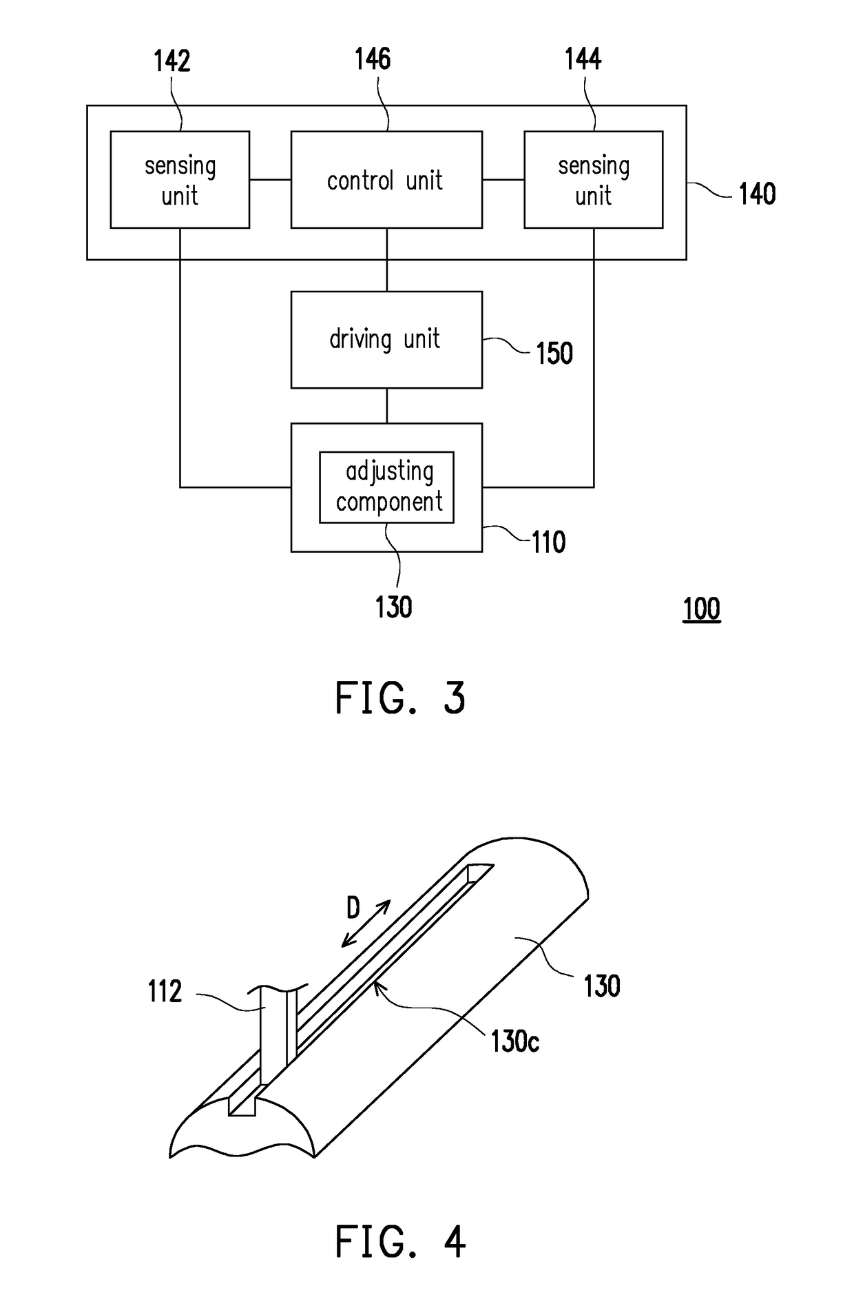
[0027]FIG. 2 illustrates the movement of an adjusting co...


PUM


Abstract

A screw expander includes a main body, at least an expansion screw and an adjusting component. The main body has a high pressure region, an expansion region and a low pressure region. The expansion screw is disposed at the expansion region and has an air inlet end and an air outlet end, wherein the air inlet end is connected to the high pressure region, and the air outlet end is connected to the low pressure region. The adjusting component covers the expansion screw, and is adapted to move relatively to the expansion screw to change an opening area of the air inlet end or an opening area of the air outlet end, such that a pressure of an air exhausted from the air outlet end is adjusted.

Description

CROSS-REFERENCE TO RELATED APPLICATION[0001]This application claims the priority benefit of Taiwan application serial no. 106121001, filed on Jun. 23, 2017. The entirety of the above-mentioned patent application is hereby incorporated by reference herein and made a part of this specification.BACKGROUNDTechnical Field[0002]The disclosure relates to an expander, particularly related to a screw expander.Description of Related Art[0003]With the development of industrialization, human demand for electricity has increased accordingly. Therefore, many of power generation methods have developed. Among them, the screw expander is driven by an input of high pressure air, and thus generates power.[0004]In general, the greater the differences between the pressure of an air outlet end of the screw expander and the pressure of an exhausted air reaching the low pressure region are, the greater the power consumption is. Therefore, how to effectively control the pressure of the air outlet end of the...

Claims


Application Information

Patent Timeline
IPC IPC(8): F01D17/14F01D17/08F01D5/02
CPCF01D17/141F01D17/08F01D5/023F05D2240/24F05D2240/12F05D2270/3011F05D2270/3013F01C1/16F01C20/12F04C2210/221
Inventor LIU, YAO-CHUNG
Owner FUSHENG IND CO LTD
Learn More