Tank system for a reducing agent

Active Publication Date: 2018-12-27
VITESCO TECH GMBH
View PDF7 Cites 1 Cited by
  • Summary
  • Abstract
  • Description
  • Claims
  • Application Information

AI Technical Summary

Benefits of technology

[0011]According to a further advantageous aspect, in which not all parts of the heating device are disposed in the lower vessel wall, the part of the heating device that is not disposed in the lower vessel wall and thus in the interior of the vessel can comprise at least one support on which further components required for the operation of the tank system are disposed. Such components can toe filters or sensors. The at least one support can be connected to the main body of the heat conducting structure, or to one or a plurality of shaped elements. It is likewise possible for supports to be disposed on the heating elements or on the connectors for the electrical contact of the heating elements. The support herein can be configured so as to be integral to the corresponding part of the heating device, or can be connected thereto in an integral manner. The provision of at least one support has the advantage that the support can be configured in a manner corresponding to the disposal of the respective component. The corresponding configuration is understood as the positioning of the respective component in the vessel and/or the fastening to the support. The support can thus support, for example, a filling level sensor, wherein the support is configured in such a manner that the filling level sensor is positionable at the lowest point, a point that is sufficiently deep for the measurement, or so as to be referenced to the base, meaning so as to be in contact with the inner side of the lower vessel wall.
[0012]By way of the disposal of at least parts of the heating device in the lower vessel wall it is ensured that a liquid, and thus conveyable reducing agent, is provided in this part of the base in the operation of the tank system. Since the heating effect acts both into the interior of the vessel as well as toward the outside, the region of the base that receives at least parts of the heating device for avoiding an emission of non-utilized heat can delimit a volume that is disposed on the outer side of the vessel. This region of the base thus delimits not only the volume located outside the vessel but also

Problems solved by technology

The complex fastening of the heating device, in particular of the heat conducting structure, to the vessel wall is disadvan

Method used


Image

  • Tank system for a reducing agent
  • Tank system for a reducing agent

Examples


Example

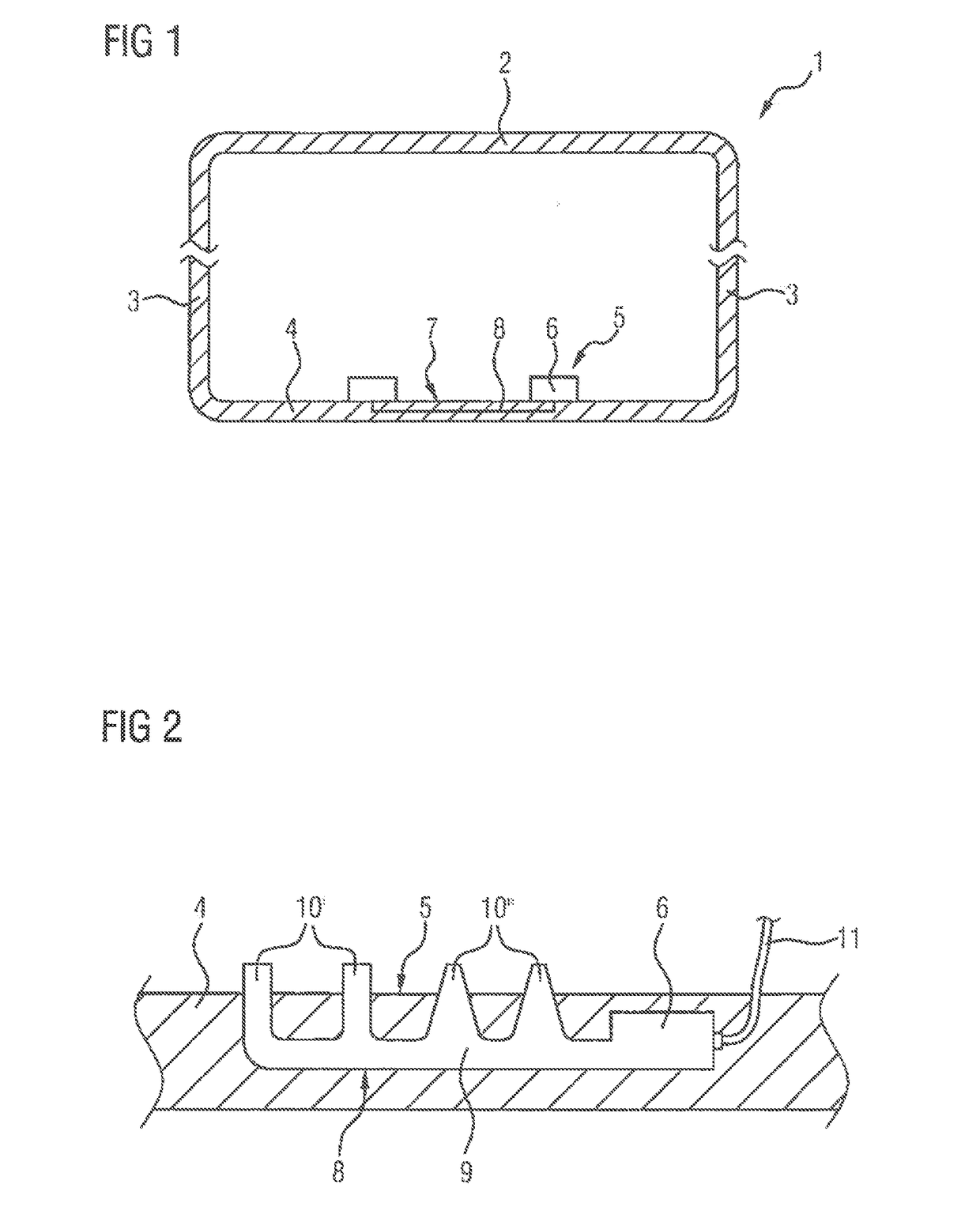
[0020]FIG. 1 schematically shows a tank system having a vessel 1, which contains urea solution as the reducing agent. The vessel 1 in the installed position has an upper vessel wall 2, a filling portion (not illustrated) for the reducing agent, lateral vessel walls 3, and a lower vessel wall 4. The lower vessel wall 4 forms the base 7 of the vessel 1. The vessel 1 is composed of plastics. However, it is also conceivable for the vessel 1 to be produced from metal. The lower vessel wall 4 has a heating device 5. The heating device 5 is composed of heating elements 6 which are fastened to the base 7 of the vessel 1, and of a heat conducting structure 8 which, connected to the heating element 6, is disposed in the lower vessel wall 4.

[0021]FIG. 2 shows an enlarged illustration of the lower vessel wall 4, having the part of the base 7 in which the heating device 5 is disposed. The heating element 6 and the heat conducting structure 8 are here disposed in the base 7 of the vessel 1. The h...


PUM


Abstract

A tank system for a reducing agent includes: a vessel configured to store the reducing agent, the vessel having: an upper vessel walk lateral vessel walls, and a lower vessel wall configured to form a base of the vessel; and a heating device disposed in the vessel. At least parts of the heating device are disposed in a part of the base of the lower vessel wall of the vessel.

Description

CROSS REFERENCE TO RELATED APPLICATIONS[0001]This is a U.S. national stage of application No. PCT / EP2016 / 080017 filed on Dec. 7, 2016, which claims priority to the Germany Application No. 10 2015 224 904.2 filed Dec. 10, 2015, the content of both incorporated herein by reference.BACKGROUND OF THE INVENTION1. Field of the Invention[0002]The invention relates to a tank system for a reducing agent.2. Related Art[0003]It is known for reducing agents to be added to the exhaust gases of motor vehicles to reduce undesirable component parts, in particular nitrogen oxide compounds, of the exhaust gas, in that nitrogen oxide compounds are converted to other compounds such as nitrogen, water, and carbon dioxide. A 32.5% urea solution which is also available under the AdBlue trademark, is used herein as the reducing agent. A vessel from which the urea solution is conveyed to the exhaust gas line is provided for providing and storing the urea solution in motor vehicles. The urea solutions that a...

Claims


Application Information

Patent Timeline
IPC IPC(8): F01N3/20
CPCF01N3/208F01N2240/16F01N2560/12F01N2610/02F01N2610/105F01N2610/142F01N2610/1486F01N3/2066F01N2610/10F01N2610/1406Y02T10/12
Inventor BRUCK, ROLF
Owner VITESCO TECH GMBH
Why Eureka
Try Eureka