Control system for an internal combustion engine
- Summary
- Abstract
- Description
- Claims
- Application Information
AI Technical Summary
Benefits of technology
Problems solved by technology
Method used
Image
Examples
first embodiment
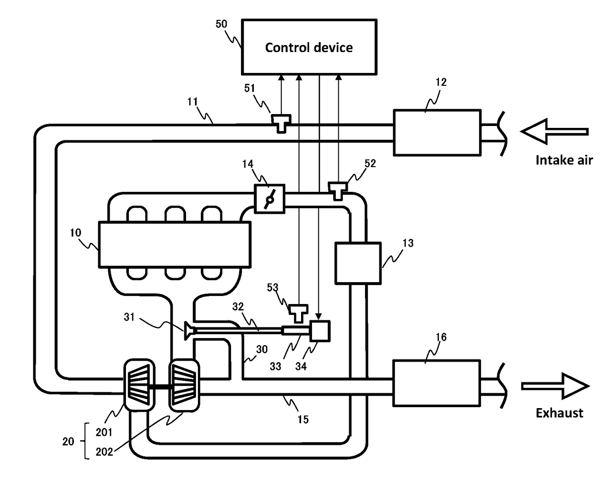
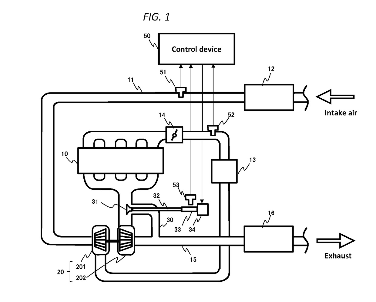
[0037]FIG. 1 is a system configuration diagram of an engine control apparatus for an engine according to a first embodiment of the present invention. In FIG. 1, an air cleaner 12 is attached to an inlet of an intake passage 11 of the engine 10. On the downstream side of the air cleaner 12, an air flow sensor 51 for detecting an intake air quantity is set.
[0038]A turbocharger 20 is provided in the downstream of the air flow sensor 51. The turbocharger 20 includes a compressor 201 and a turbine 202. The compressor 201 and the turbine 202 are coupled together by a connecting shaft. The compressor 201 is driven to rotate by fluid energy of the exhaust gas input to the turbine 202. Then, an intercooler 13 for cooling the compressed air is disposed in the downstream of the compressor 201. A throttle valve 14 is disposed in the downstream of the intercooler 13. Further, a boost pressure sensor 52 for detecting the pressure of the supercharged intake air is provided between the intercooler ...
PUM
 Abstract
Description
Claims
Application Information
 - R&D
- Intellectual Property
- Life Sciences
- Materials
- Tech Scout
- Unparalleled Data Quality
- Higher Quality Content
- 60% Fewer Hallucinations
Browse by: Latest US Patents, China's latest patents, Technical Efficacy Thesaurus, Application Domain, Technology Topic, Popular Technical Reports.
© 2025 PatSnap. All rights reserved.Legal|Privacy policy|Modern Slavery Act Transparency Statement|Sitemap|About US| Contact US: help@patsnap.com


