Optically transparent plate with light emitting function and method of producing the same

Active Publication Date: 2018-12-27
STANLEY ELECTRIC CO LTD
View PDF4 Cites 4 Cited by
  • Summary
  • Abstract
  • Description
  • Claims
  • Application Information

AI Technical Summary

Benefits of technology

[0009]According to the present invention, the light extraction efficiency can be improved, even

Problems solved by technology

This is because, when the LED die is bonded to a board via die-bonding or wire-bonding, a temperature at which the substrate is heated (180° C. or higher) may cause deformation of the plastic substrate.
As for the organic EL element, it can be directly mounted on a resin film, but since the organic EL is vulnerable to moisture, it i

Method used


Image

  • Optically transparent plate with light emitting function and method of producing the same
  • Optically transparent plate with light emitting function and method of producing the same
  • Optically transparent plate with light emitting function and method of producing the same

Examples


Example

First Embodiment

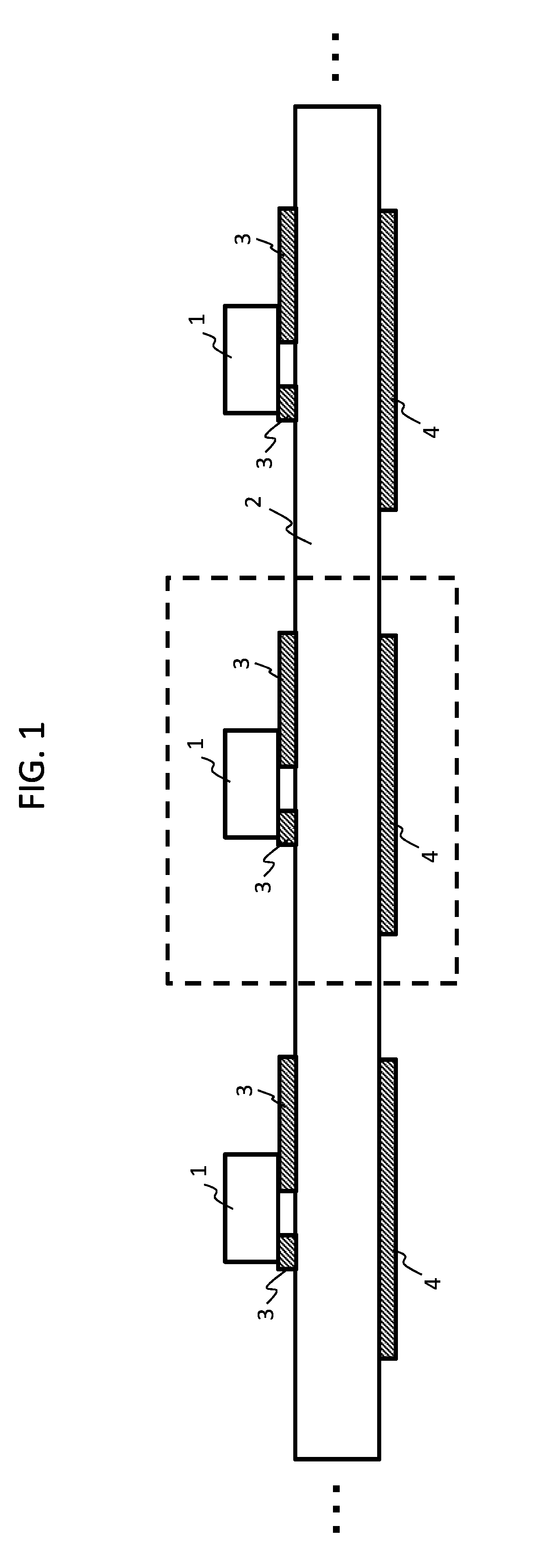
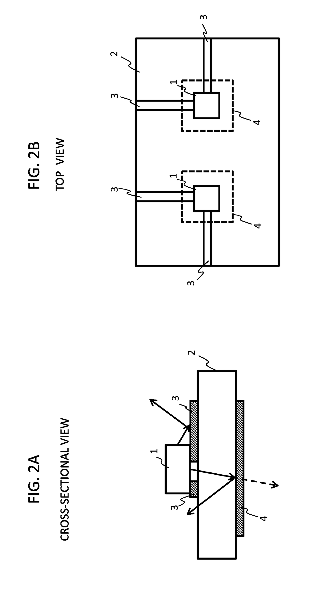
[0042]An optically transparent plate with a light emitting function according to a first embodiment comprises an optically transparent substrate 2, a wiring pattern 3 provided on a surface of the optically transparent substrate 2, and an LED die 1 bonded to the wiring pattern 3, as illustrated by a cross-sectional view of FIG. 1 and a partial cross-sectional view and a top view of FIGS. 2A and 2B. A reflective layer 4 is placed on the underside of a region where the LED die 1 is mounted on the optically transparent substrate 2. Both at least a part of the wiring pattern 3 and the reflective layer 4 comprise a conductive material obtained by sintering conductive particles. In addition, the LED die 1 is bonded to the wiring pattern 3 via the conductive material obtained by sintering the conductive particles.

[0043]As described above, the wiring pattern 3 is made of conductive material obtained by sintering conductive particles, and in addition, the LED die 1 is bonded t...

Example

Second Embodiment

[0084]With reference to FIGS. 10A to 100 and FIGS. 11A to 11E, there will now be described the optically transparent plate with the light emitting function according to a second embodiment.

[0085]As shown in FIG. 10A, similar to the first embodiment, the optically transparent plate with the light emitting function according to the second embodiment is provided with the optically transparent substrate 2, the wiring pattern 3 placed on the surface of the optically transparent substrate 2, and the LED die 1 bonded to the wiring pattern 3. At least a part of the wiring pattern 3 comprises a conductive material obtained by sintering the conductive particles, and the LED die 1 is bonded to the wiring pattern 3 via the conductive material obtained by sintering the conductive particles. The same reference numerals as those of the first embodiment denote the same configurations as those of the first embodiment.

[0086]In the second embodiment, a notch 11 is provided in the vici...

Example

Third Embodiment

[0109]With reference to FIGS. 21 to 23, the optically transparent plate with the light emitting function according to a third embodiment will be described.

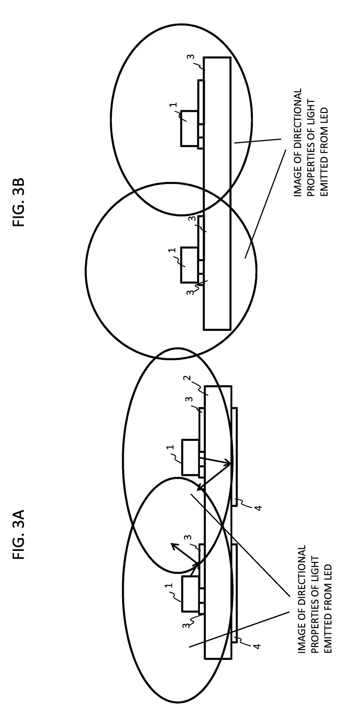
[0110]As described in the first embodiment with reference to FIGS. 3 to 6, the optically transparent plate provided with the reflective layer 4 of the present embodiment is allowed to improve color mixture properties when multiple LED dies 1 are mounted, each having different wavelengths of emitted light. In the third embodiment, there will be described another configuration of the optically transparent plate with improved color mixture properties.

[0111]FIG. 21A is a partial cross-sectional view showing the optically transparent plate with the light emitting function according to the third embodiment, and it has a similar configuration as the optically transparent plate according to the first embodiment as shown in FIG. 5. However, in the third embodiment, the reflective layer 4 placed on the underside of the optic...


PUM


Abstract

Provided is an optically transparent plate having a structure where an LED die is directly mounted on an optically transparent substrate, and light extraction efficiency is improved. The optically transparent plate comprises, an optically transparent substrate, a wiring pattern placed on either of a surface on the upper side and a surface on the underside of the optically transparent substrate, or on both of the surfaces, and the LED die bonded to the wiring pattern. A reflective layer is placed on the other side, of the surface of the optically transparent substrate on which the LED die is mounted. At least a part of the wiring pattern and at least a part of the reflective layer comprise a conductive material obtained by sintering conductive particles.

Description

FIELD OF THE INVENTION[0001]The present invention relates to an optically transparent plate, equipped with one or more light sources and capable of emitting light.DESCRIPTION OF THE RELATED ART[0002]The Japanese unexamined patent application publication No. 2008-234595 (hereinafter, referred to as “Patent Document 1”) discloses that an LED is mounted on a plastic substrate such as a credit card, and a color of light emission therefrom is made to vary, thereby presenting payment information. The Japanese unexamined patent application publication No. 2008-217215 (hereinafter, referred to as “Patent Document 2”) discloses that an organic EL luminous panel is mounted on a plastic IC card, and a remaining payment amount is displayed according to luminous positions or luminous patterns.[0003]The Japanese unexamined patent application publication No. 2016-184621 (hereinafter, referred to as “Patent Document 3”) discloses that a transparent substrate is coated with a solution containing con...

Claims


Application Information

Patent Timeline
IPC IPC(8): H01L25/13H01L33/60H01L33/62
CPCH01L25/13H01L33/60H01L33/62H01L33/48H01L25/0753H01L25/0756H01L33/405
Inventor TADA, REIKIHANYA, AKIHIKO
Owner STANLEY ELECTRIC CO LTD
Why Eureka
Try Eureka