
OLED display panel and method for manufacturing the same, and display device

a technology of oled display panel and display device, which is applied in the field of display, can solve the problems of reducing the display quality of the oled display panel, and achieve the effect of effectively eliminating the phenomenon of light leakage and improving the display quality of the oled display

Active Publication Date: 2018-12-27
WUHAN CHINA STAR OPTOELECTRONICS SEMICON DISPLAY TECH CO LTD
View PDF1 Cites 9 Cited by
  • Summary
  • Abstract
  • Description
  • Claims
  • Application Information

AI Technical Summary

Benefits of technology

The present disclosure provides an OLED display panel and a method for manufacturing the same that can effectively improve display quality by eliminating the light leakage phenomenon between adjacent sub-pixels. The design features a hole blocking portion that prevents the transfer of holes between adjacent sub-pixels, creating a more stable and reliable connection between them. Overall, this technology allows for better pixel-to-pixel control and improved display quality.

Problems solved by technology

In the case where the intervals between the light emitting units decreases and the transfer performance of the first common layer increases continuously, a transverse current of the display panel also increases, which causes a crosstalk.
Especially when the target light emitting unit is lit under a low current, since the light emitted by the target light emitting unit is also weak, the performance of the light leakage phenomenon is obvious at this time, and thereby the display quality of the OLED display panel is reduced.

Method used


Image

  • OLED display panel and method for manufacturing the same, and display device
  • OLED display panel and method for manufacturing the same, and display device
  • OLED display panel and method for manufacturing the same, and display device

Examples


Embodiment Construction

[0028]In order for the purpose, technical solution and advantages of the present disclosure to be clearer, the embodiments of the present disclosure will be explained in detail below in conjunction with the drawings. These preferred embodiments are exemplified in the drawings. The embodiments of the present disclosure as shown in the drawings and as described according to the drawings are only exemplified, and the present disclosure is not limited to these embodiments.

[0029]Here, it is also worthy to note that, in order to prevent the present disclosure from being obscured due to unnecessary details, the drawings only illustrate the structure and / or processing steps closely related to the solution according to the present disclosure, while other details less related to the present disclosure are omitted.

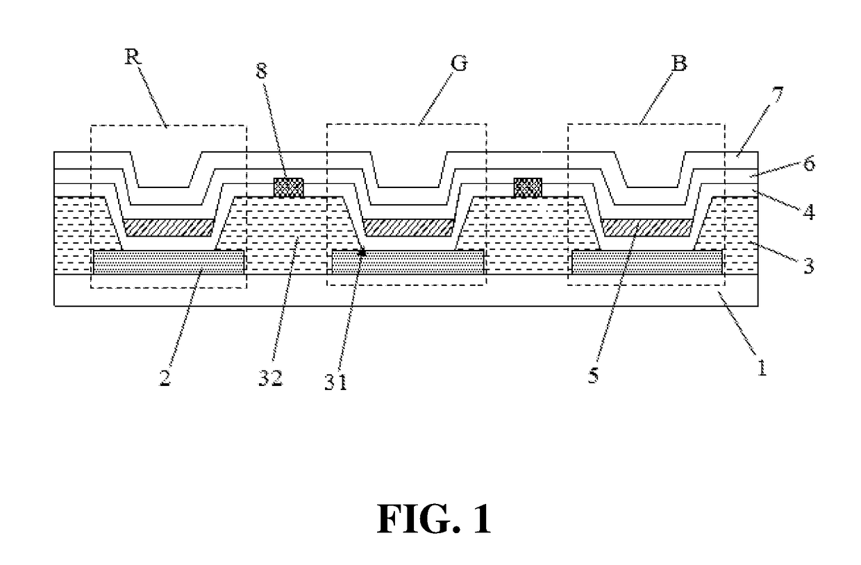
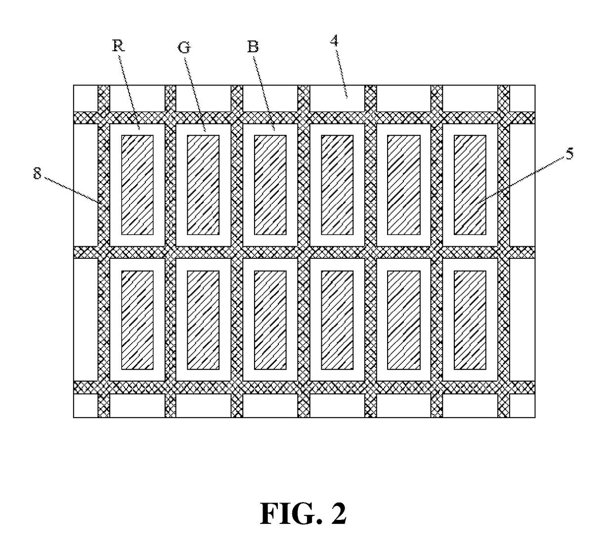
[0030]The present embodiment first provide an OLED display panel, as shown in FIG. 1, the OLED display panel includes a TFT array substrate 1 and a plurality of function layers seque...


PUM


Abstract

The present disclosure discloses an OLED display panel, including a TFT array substrate and a plurality of anodes disposed in an array on the TFT array substrate, the TFT array substrate has a pixel defining layer disposed thereon, the pixel defining layer includes opening portions and spacing portions, and each opening portion corresponds to one sub-pixel area; wherein, the pixel defining layer has a first common layer, a second common layer and a cathode layer sequentially disposed thereon, and a light emitting material is disposed between the first common layer and the second common layer corresponding to each sub-pixel area; wherein, a hole blocking portion is further disposed above the spacing portion, and the hole blocking portion spaces the first common layer between two adjacent sub-pixel areas. The present disclosure further discloses a method for manufacturing the OLED display panel as mentioned above.

Description

TECHNICAL FIELD[0001]The present disclosure relates to a display technical field, in particular to an OLED display panel and a method for manufacturing the same, and also relates to a display device including the above-mentioned OLED display panel.BACKGROUND ART[0002]An OLED (organic electroluminescent diode) display device has characteristics, such as a self-illumination, a wide view angle, a high luminous efficiency, a low power consumption, a fast responding time, a good low temperature characteristic, a simple manufacturing process, a low cost and so on, which has been widely used in the display field.[0003]A core component of the OLED display device is an OLED display panel, and a structure of the OLED display panel usually includes: a TFT array substrate and an anode layer, a pixel defining layer, a first common layer, a light emitting layer, a second common layer and a cathode layer sequentially manufactured on the TFT substrate. The anode layer includes a plurality of anodes...

Claims


Application Information

Patent Timeline
Patent Type & Authority Applications(United States)
IPC IPC(8): H01L51/50H01L27/32H01L51/52H01L51/56H01L51/00H10K99/00
CPCH01L51/5096H01L27/3211H01L27/3246H01L51/5206H01L51/5221H01L51/5036H01L51/5056H01L51/5072H01L51/56H01L51/0005H01L2227/323H01L2251/558H10K59/35H10K59/122H10K71/135H10K50/18H10K59/1201H10K50/15H10K50/16H10K50/81H10K50/82H10K50/125H10K71/00H10K2102/351
Inventor YANG, JIE
Owner WUHAN CHINA STAR OPTOELECTRONICS SEMICON DISPLAY TECH CO LTD
Learn More