
Equipotential grounding grate

a technology of grate and ground, applied in the field of grates, can solve the problems of uneven floor increasing traction between the grate and the ground, and achieve the effect of increasing traction

Active Publication Date: 2018-12-27
KLEIN PARENT LLC
View PDF4 Cites 0 Cited by
  • Summary
  • Abstract
  • Description
  • Claims
  • Application Information

AI Technical Summary

Benefits of technology

The patent describes a type of grate that is used to create a safe workplace for workers and equipment. These grates have an uneven floor with raised sections that improve their grip on the ground. This makes it easier for the grate to hold its position without being pressed into the ground. The technical effect of this design is that it provides a stable and secure path for workers and equipment to safely traverse.

Problems solved by technology

This uneven floor increases traction between the grate and the ground.

Method used


Image

  • Equipotential grounding grate
  • Equipotential grounding grate
  • Equipotential grounding grate

Examples


Embodiment Construction

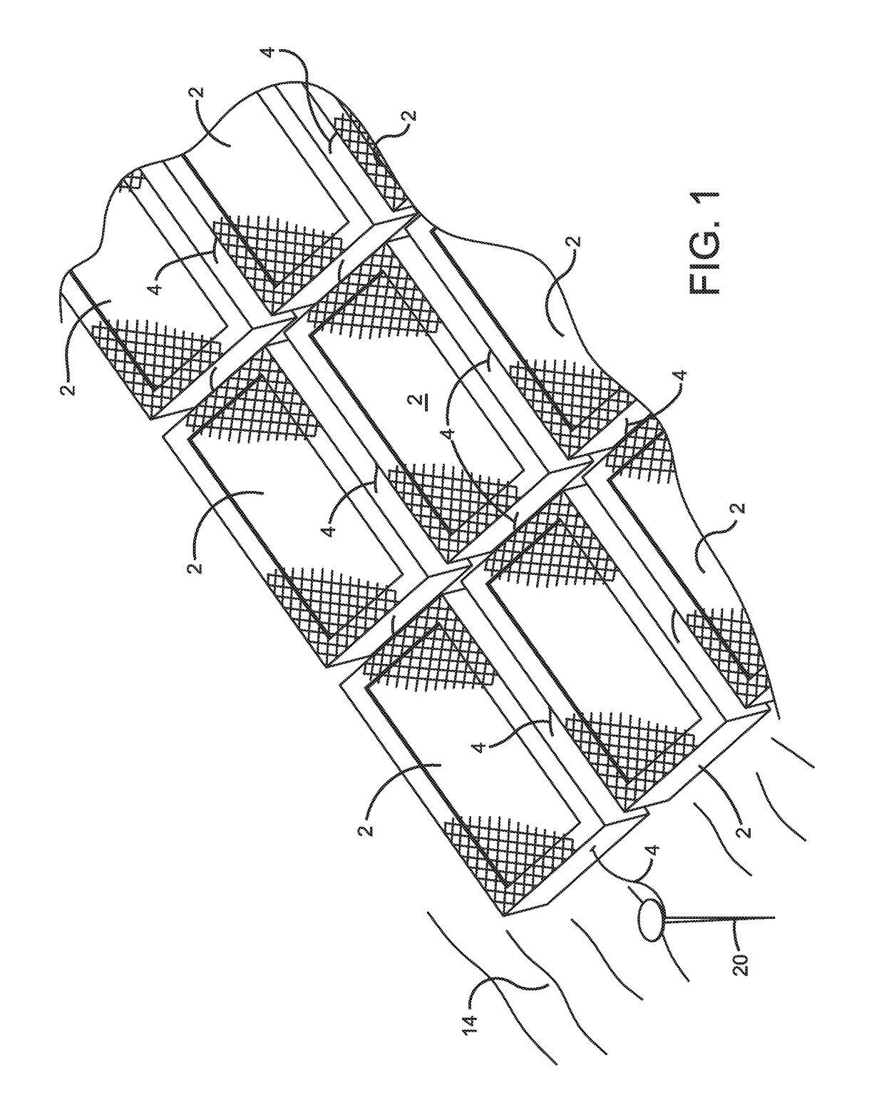
[0026]The disclosure provides exemplary configurations of electrically groundable support grates for use on or near the surface of the earth for supporting workers and equipment. A plurality of exemplary support grates 2 are depicted in FIG. 1 forming an equipotential grounding platform capable of supporting workers and equipment such as trucks. Each grate 2 can be galvanized. Grates 2 are electrically connected with flexible cables 4 that allow grates 2 to be used on uneven ground. Each grate 2 is electrically conductive and the electric connections between grates 2 combined with a grounding pin 20 create an equipotential zone or EPZ work platform. Grates 2 are provided in sizes such as 4′×8′, 4′×14′, 8′×12′, or 8′×14′. Other dimensions can be provided as desired for the different sizes of equipotential zones being created.

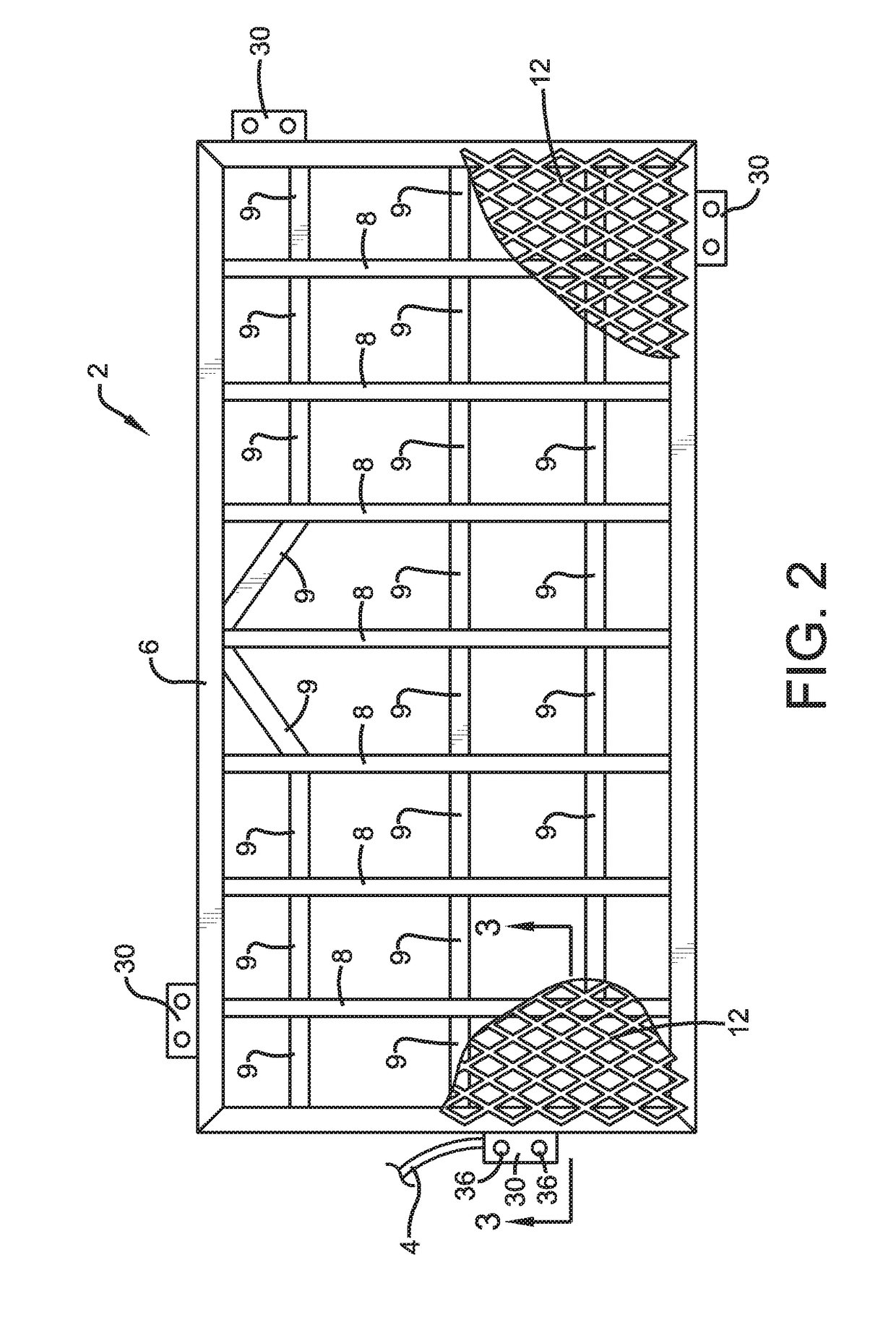
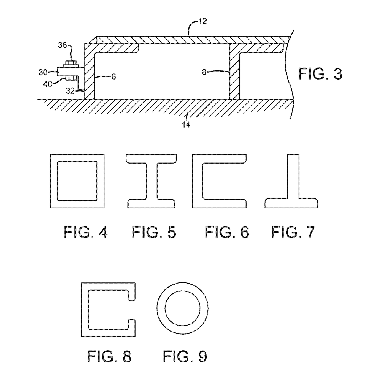
[0027]In the first exemplary configuration of FIGS. 2-9, each grate 2 includes a perimeter frame 6, a plurality of inner supports (which can be inner cross suppo...


PUM


Abstract

Self-supporting equipotential grounding grates are used to create an equipotential zone for workers and equipment. The grates have a plurality of supports that cooperate to position the upper surface of a conductive grid above the surface on which the grates are used. The inner supports include upper and lower structural grids that allow debris to be readily removed from the grate after use. The grate supports workers and equipment. A plurality of the grates are electrically connected with cables to define a platform with the entire structure grounded with one or more grounding pins.

Description

CROSS REFERENCE TO RELATED APPLICATIONS[0001]This application claims the benefit of U.S. Provisional Patent application Nos. 62 / 523,671 filed Jun. 22, 2017; 62 / 524,366 filed Jun. 23, 2017; and 62 / 566,972 filed Oct. 2, 2017; the disclosures of each are incorporated herein by reference.BACKGROUND OF THE INVENTION1. Field of Invention[0002]This disclosure generally relates to equipotential grounding structures for bonded work zones, and, more particularly, to grates that are self-supporting and do not require an underlying solid mat for support.2. Description of Related Art[0003]Existing equipotential grounding mats include a wood mat—such as a timber access mat—combined with a removable conductive cover that is re-usable after the wood mat deteriorates. Another example uses a polymer mat below a metal cover. U.S. Pat. Nos. 9,458,578 and 9,368,918 disclose examples of these devices. These devices are used to create an equipotential ground and bonded work zone. The devices are positione...

Claims


Application Information

Patent Timeline
Patent Type & Authority Applications(United States)
IPC IPC(8): H01R13/648E01C9/08
CPCH01R13/648E01C9/08E01C9/083H05F3/025
Inventor KLEIN, ERIK D.
Owner KLEIN PARENT LLC
Learn More