A coating ablating apparatus with coating removal detection

a technology of coating removal and coating ablating equipment, which is applied in the direction of metal-working equipment, welding equipment, manufacturing tools, etc., can solve the problems of surface damage, possible damage, and inability to work well, and achieve the effect of preventing surface damag

Active Publication Date: 2019-01-03
GEN LASERTRONICS
View PDF0 Cites 3 Cited by
  • Summary
  • Abstract
  • Description
  • Claims
  • Application Information

AI Technical Summary

Benefits of technology

[0005]Embodiments of the present invention are directed to a laser-based coating removal apparatus to remove a coating from a surface without damaging the surface. The apparatus comprises a laser source to provide a laser light, a routing element coupled to the laser source and configured to direct the laser light onto a target region of the surface thereby removing the coating from the target region, and a detection element to detect the coating as the coating separates from the target region of the surface. The detection element is able to prevent the surface from being damaged by limiting or eliminating the laser light directed onto the target region after all the coating has been removed. The detection element is able to detect the separation of the coating from the target region by detecting incandescence, acoustic signature, motion, fluorescence and / or chemical properties produced by the separation of the coating from the surface.

Problems solved by technology

A problem with laser de-coating systems is the possibility of damaging the surface if the stripping process is continued after all the coating is removed.
A particular source of the possible damage is the result of overheating the surface due to the absorption of the excess laser light by the surface after the coating has been removed.
However, these techniques do not work well if the distance and the angle from the laser optics to the substrate vary widely as is the case in many handheld laser de-coating systems on non-flat surfaces.

Method used


Image

  • A coating ablating apparatus with coating removal detection
  • A coating ablating apparatus with coating removal detection
  • A coating ablating apparatus with coating removal detection

Examples


Embodiment Construction

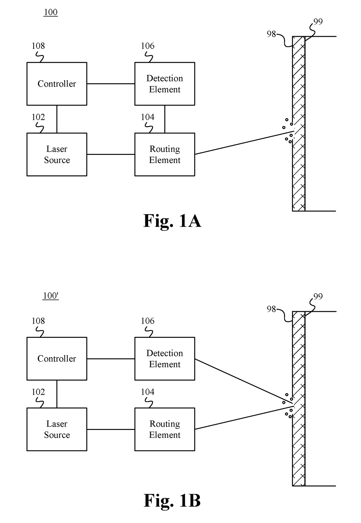
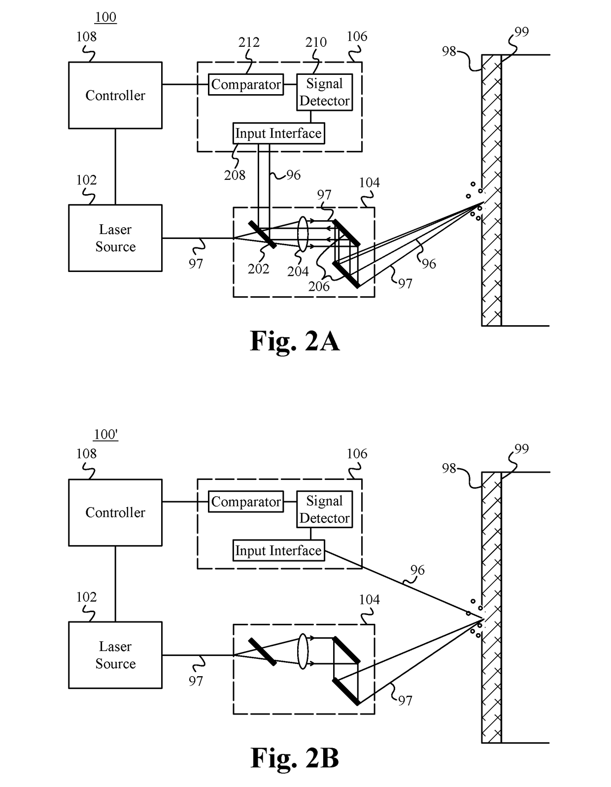
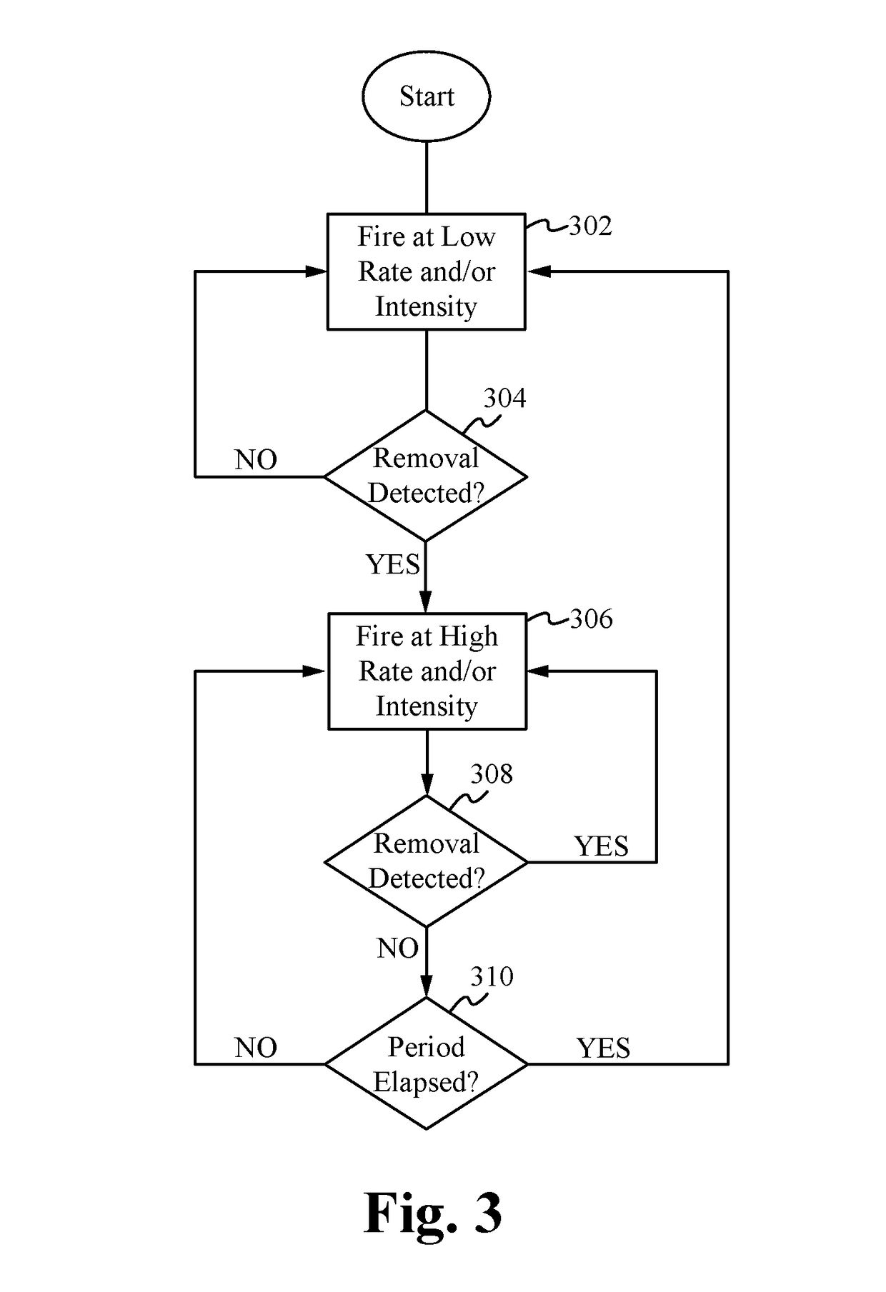
[0015]Embodiments of the present invention are directed to a laser-based coating removal apparatus to remove a coating from a surface without damaging the surface. The apparatus comprises a laser source to provide a laser light, a routing element coupled to the laser source and configured to direct the laser light onto a target region of the surface thereby removing the coating from the target region, and a detection element to detect the coating as the coating separates from the target region of the surface. The detection element is able to prevent the surface from being damaged by limiting or eliminating the laser light directed onto the target region after all the coating has been removed. The detection element is able to detect the separation of the coating from the target region by detecting incandescence, acoustic signature, motion, fluorescence and / or chemical properties produced by the separation of the coating from the surface.

[0016]Reference will now be made in detail to i...


PUM

PropertyMeasurementUnit
energyaaaaaaaaaa
lengthaaaaaaaaaa
fluorescenceaaaaaaaaaa

Abstract

A laser-based coating removal apparatus to remove a coating from a surface without damaging the surface. The apparatus comprises a laser source to provide a laser light, a routing element coupled to the laser source and configured to direct the laser light onto a target region of the surface thereby removing the coating from the target region, and a detection element to detect the coating as the coating separates from the target region of the surface. The detection element is able to prevent the surface from being damaged by limiting or eliminating the laser light directed onto the target region after all the coating has been removed. The detection element is able to detect the separation of the coating from the target region by detecting incandescence, acoustic signature, motion, fluorescence and / or chemical properties produced by the separation of the coating from the surface.

Description

RELATED APPLICATIONS[0001]This application claims priority of U.S. provisional application, Ser. No. 61 / 362,976, filed Jul. 9, 2010, and entitled “Non-Color Sensing for Laser Decoating,” which is incorporated herein by reference.FIELD OF THE INVENTION[0002]The invention relates to ablating a coating using a laser. In particular, the invention relates to a coating ablating apparatus for detecting the removal of a coating from a surface using a laser to prevent surface damage.BACKGROUND OF THE INVENTION[0003]Laser-based coating removal systems use pulses of light from high power lasers to ablate or vaporize the paint or other coating from a surface. Each pulse removes the coating from a small region, typically 0.1 to 100 square mm. The laser is pointed to a different area after each pulse, where the removal process is repeated until the entire surface is cleaned. An advantage of lasers for coating removal is that each laser pulse removes a predictable portion of the thickness of the c...

Claims


Application Information

Patent Timeline
Patent Type & Authority Applications(United States)
IPC IPC(8): B23K26/03
CPCB23K26/032B23K26/361
Inventor THOMAS, JAMES W.NOEL, RAYMOND J.WOOL, MITCHELL R.
Owner GEN LASERTRONICS
Why Eureka
Try Eureka