Device for detecting deformation of a hollow component

Inactive Publication Date: 2019-01-03
DEPUY (IRELAND) LTD
View PDF6 Cites 2 Cited by
  • Summary
  • Abstract
  • Description
  • Claims
  • Application Information

AI Technical Summary

Benefits of technology

[0041]The device may be preassembled within the hollow component. This ensures that the correct device is being used in conjunction with the hollow component. It can eliminate need to fit the device inside the hollow component prior to deployment of the hollow component.
[0042]In particular, the kit may include the device of the invention and an orthopaedic component. The component can be an implantable component of a joint prosthesis, for example, an acetabular cup component of a hip prosthesis, a glenoid component of an anatomic shoulder joint prosthesis or a humeral component of a reverse shoulder joint

Problems solved by technology

A change in the distance between the first and second points on opposite sides of the f

Method used


Image

  • Device for detecting deformation of a hollow component
  • Device for detecting deformation of a hollow component
  • Device for detecting deformation of a hollow component

Examples


Embodiment Construction

[0052]The invention will now be described, by way of example only, with reference to the following drawings, in which:

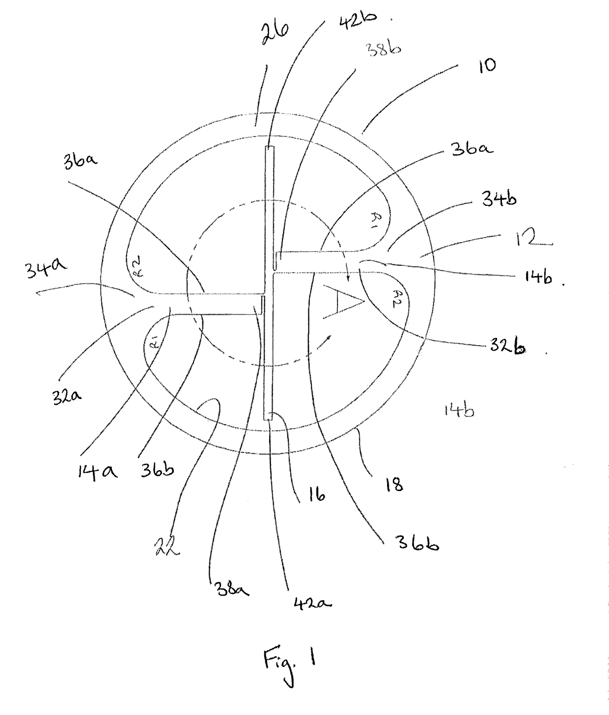
[0053]FIG. 1 is a top elevation view of a first construction of a device for detecting deformation of a hollow component in an un-deformed state.

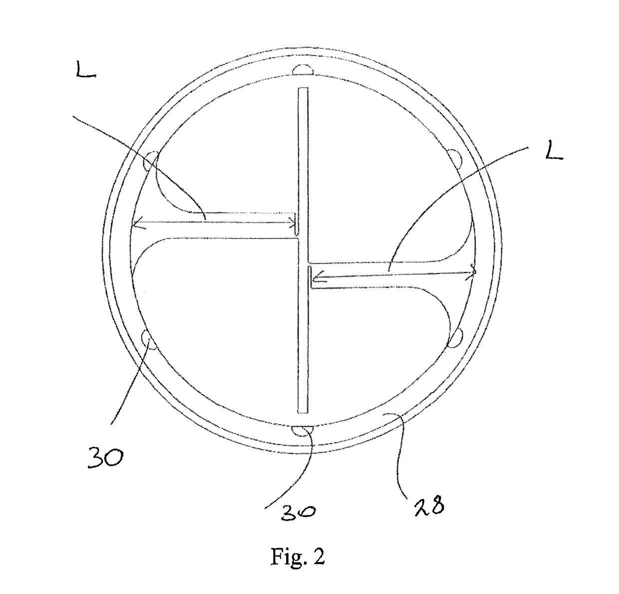
[0054]FIG. 2 is a bottom elevation view of the device of FIG. 1.

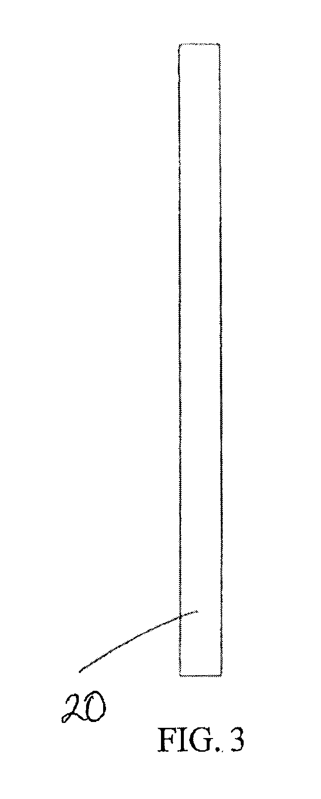
[0055]FIG. 3 is a side elevation view of the device of FIG. 1.

[0056]FIG. 4 is a perspective view of the device of FIG. 1

[0057]FIG. 5 is an enlarged view of the area “A” of the device of FIG. 1.

[0058]FIG. 6 is a top elevation view of the device of FIG. 1 for detecting deformation of a hollow component in a deformed state following the application of compressive forces to the device in the direction of the arrows A.

[0059]FIG. 7 is a top elevation view of the device for detecting deformation of a hollow component in a deformed state following the application of compressive forces to the device in the direction of the arrows B.

[0060]FIG. 8 is a top elevation view of...


PUM


Abstract

The invention provides a device for fitting into a hollow component to provide an indication of whether the hollow component has been deformed, which includes a frame which can be fitted in the) component, and an elongate indicator suspendedly connected to the frame, with any deformation of the frame being visualised as a deflection of the indicator.

Description

FIELD OF THE INVENTION[0001]The present invention relates to a device for detecting the deformation of a hollow component and methods of using the device. In particular, the present invention concerns a device for detecting the deformation of a hollow orthopaedic component, such as a cup component of an orthopaedic joint prosthesis.BACKGROUND TO THE INVENTION[0002]Press-fit fixation is a common technique for implanting components of an orthopaedic prosthesis that eliminates the need for supplementary fixation such as cement, screws or spikes. Short term stability of the implant is achieved through an interference fit between the implant and the surrounding bone. Long term stability is achieved through bone ingrowth or on growth, which is typically aided by an exterior roughened or porous surface. Such fixation techniques are applicable to fixation of cup components of orthopaedic joint prostheses. They are applicable for example to fixation of an acetabular component of a hip joint ...

Claims


Application Information

Patent Timeline
IPC IPC(8): G01B21/32G01B21/22A61F2/46A61F2/34
CPCG01B21/32G01B21/22A61F2/4609A61F2/34A61F2/4657A61B17/1746A61F2002/30471A61F2002/30617A61B2090/0811
Inventor BAILEY, ANDREWPRINCE, STEPHANIEYOUNG, DUNCAN
Owner DEPUY (IRELAND) LTD
Why Eureka
Try Eureka