
Battery pack comprising member of edge cooling type

a battery pack and edge cooling technology, applied in the field of batteries, can solve the problems of accelerating the deterioration of the battery cell, difficult to effectively reduce the temperature of all the battery cells, and large heat generation of high-output large-capacity rechargeable batteries, and achieve the effect of high thermal conduction efficiency

Active Publication Date: 2019-01-03
LG ENERGY SOLUTION LTD
View PDF6 Cites 0 Cited by
  • Summary
  • Abstract
  • Description
  • Claims
  • Application Information

AI Technical Summary

Benefits of technology

The present invention is a battery pack with high thermal conduction efficiency that can be used as a power source for small devices requiring a high current discharge such as drones. The battery pack can be used in various devices such as mobile electronic devices, power tools, electric vehicles, electric golf carts, and power storage systems.

Problems solved by technology

Since the battery cells included in the middle- or large-sized battery pack are rechargeable batteries, a high-output large-capacity rechargeable battery generates a large amount of heat during a charging and discharging process.
Particularly, since the laminate sheet of the pouch-type battery widely used in the battery pack is coated with a polymer material having low thermal conductivity, it is difficult to effectively reduce a temperature of all of the battery cells.
When heat generated during the charging and discharging process is not effectively eliminated, heat accumulation may occur, which may accelerate deterioration of the battery cell and possibly cause ignition or explosion.
In addition, since the cooling fins and the cooling members are thermally coupled to each other with a heat radiation pad therebetween and the cooling member is formed with a coolant channel, manufacturing cost is increased and a manufacturing process is complicated.

Method used


Image

  • Battery pack comprising member of edge cooling type
  • Battery pack comprising member of edge cooling type
  • Battery pack comprising member of edge cooling type

Examples


Embodiment Construction

[0053]Hereinafter, an exemplary embodiment of the present invention is described with reference to the drawings, but the scope of the present invention is not limited thereto.

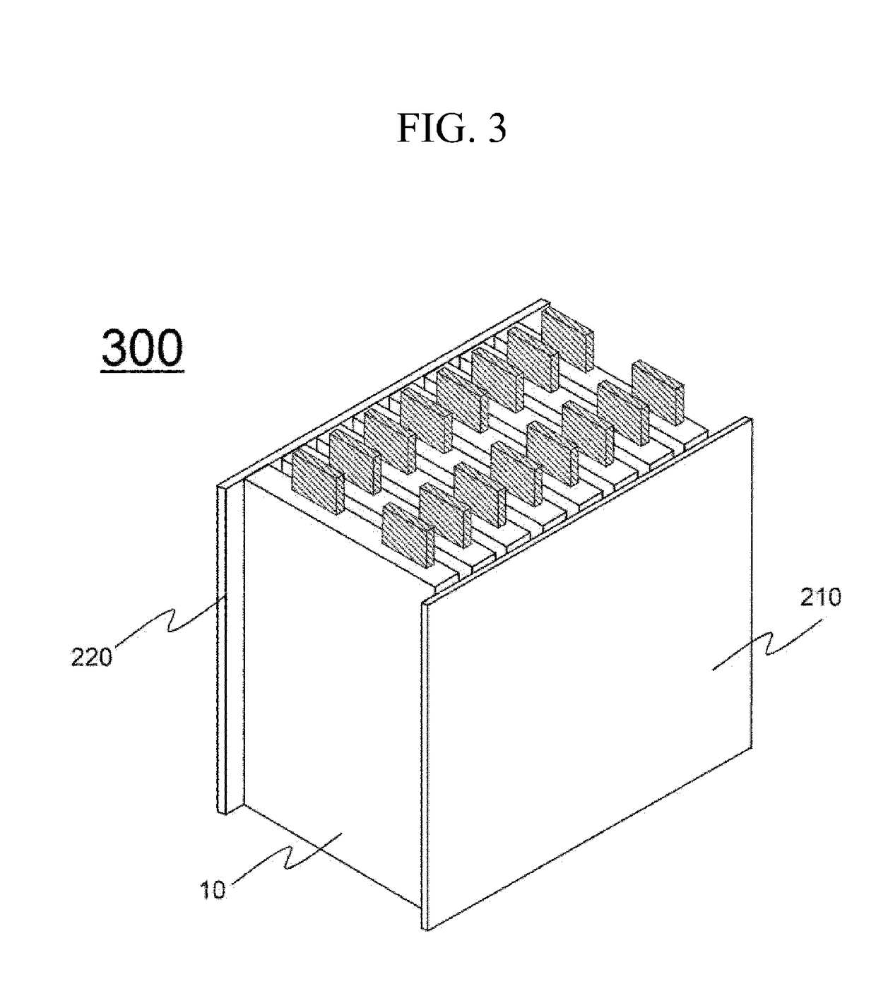
[0054]FIG. 3 illustrates a schematic view of a structure of a battery pack according to an exemplary embodiment of the present invention, and FIG. 4 illustrates a top plan view of the battery pack of FIG. 3.

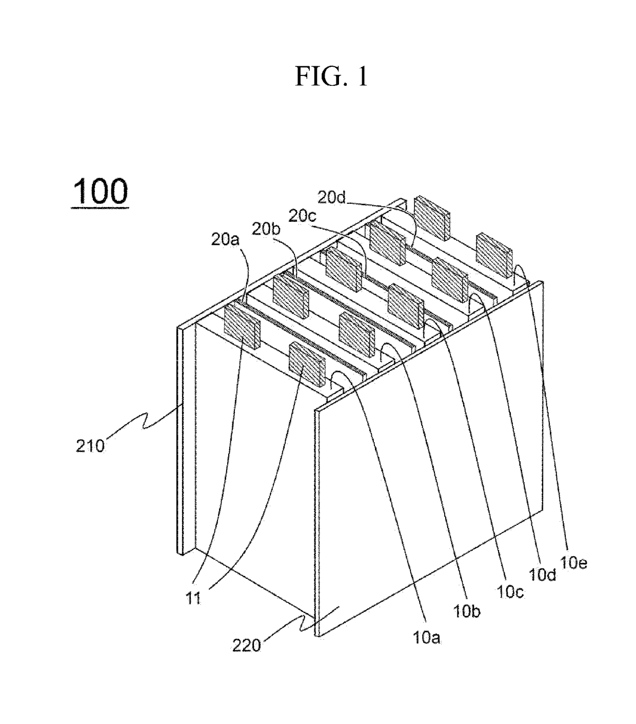
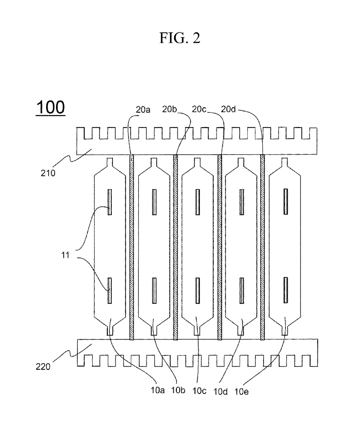
[0055]Referring to FIG. 3 and FIG. 4, a battery pack 300 includes a battery cell assembly 200 in which a plurality of battery cells 10 are stacked while directly facing each other, and cooling members 210 and 220 positioned to be perpendicular to a stacking direction of the battery cells.

[0056]A first surface 201 and a second surface 202 of the battery cell assembly 200 perpendicular to the stacking direction of the battery cells 10 are positioned to face each other based on an electrode terminal 11 of the battery cells. The cooling members 210 and 220 include a first cooling member 210 and a second cooling ...


PUM

PropertyMeasurementUnit
angleaaaaaaaaaa
shapeaaaaaaaaaa
thermal conductionaaaaaaaaaa

Abstract

A battery pack including: a battery cell assembly in which a plurality of chargeable and dischargeable battery cells are stacked; and a pair of cooling members configured to eliminate heat generated during charging and discharging of the battery cells, wherein the cooling members may include first and second cooling members positioned on first and second surfaces of the battery cell assembly perpendicular to a direction in which the battery cells are stacked, and an inner surface of each of the first cooling member and the second cooling member may be formed with a thermal contact portion with a shape of being in close contact with an outer surface of each of the first and second surfaces of the battery cell assembly for thermal conduction, is provided.

Description

TECHNICAL FIELD[0001]This application claims the benefit of Korean Patent Application No. 10-2016-0001310 on Jan. 6, 2016 with the Korean Intellectual Property Office, the disclosure of which is herein incorporated by reference in its entirety.[0002]The present invention relates to a battery pack in which a thermal contact portion for thermal conduction is formed on an inner surface of a cooling member.BACKGROUND ART[0003]Recently, a rechargeable battery that can be repeatedly charged and discharged has been variously used as an energy source of a wireless mobile device. In addition, the rechargeable battery has attracted attention as an energy source of an electric vehicle (EV), a hybrid electric vehicle (HEV), a plug-in hybrid electric vehicle (PHEV), and the like, which have been proposed as a solution to solve air pollution from conventional gasoline vehicles and diesel vehicles using fossil fuels.[0004]In small-sized mobile devices, one or more battery cells are used per device...

Claims


Application Information

Patent Timeline
Patent Type & Authority Applications(United States)
IPC IPC(8): H01M10/647H01M10/613H01M10/6554H01M10/6551H01M2/02H01M50/105H01M50/211
CPCH01M10/647H01M10/613H01M10/6554H01M10/6551H01M2/0207H01M10/6567H01M10/6561Y02E60/10H01M50/105H01M50/211
Inventor NAM, HO CHOLYOON, HYOUNG CHULKIM, DONG HYUNYOON, SEOG JIN
Owner LG ENERGY SOLUTION LTD
Learn More