
Light-transmitting substrate, display device, signal device, and illumination device

a technology of light-transmitting substrates and substrates, which is applied in the direction of light sources, electrical equipment, construction, etc., can solve the problems of difficult to achieve large electric power required for melting snow, and inability to efficiently conduct the heat generated by the heater to the surface of the acrylic resin plate. achieve the effect of high thermal conduction efficiency

Active Publication Date: 2019-02-26
STANLEY ELECTRIC CO LTD
View PDF80 Cites 0 Cited by
  • Summary
  • Abstract
  • Description
  • Claims
  • Application Information

AI Technical Summary

Benefits of technology

The present invention provides a thin light-transmitting substrate that can effectively raise surface temperature while maintaining high thermal conduction efficiency.

Problems solved by technology

However, since both air and acrylic resin plate have a low thermal conductivity (about 0.17 to 0.25 W / mK at ordinary temperature), and therefore they cannot efficiently conduct the heat generated by the heater to the surface of the acrylic resin plate.
Therefore, it is difficult to obtain high thermal conduction efficiency with this unit, and electric power required for melting snow becomes large.
Further, since it employs the structure that the internal space is formed, rigidity is required for the acrylic resin plates, and therefore even if it is desired to make the acrylic resin plates of the snow-melting unit thinner in order to improve the thermal conduction efficiency, and obtain a thinner unit, it is difficult to do so more than a certain extent.
Furthermore, since the unit suffers from low thermal conduction efficiency, and requires much electric power for melting snow, it is necessary to use a heater having a diameter larger than a certain extent, and thus it becomes difficult to see the sign displayed on the LED display through the snow-melting unit.

Method used


Image

  • Light-transmitting substrate, display device, signal device, and illumination device
  • Light-transmitting substrate, display device, signal device, and illumination device
  • Light-transmitting substrate, display device, signal device, and illumination device

Examples


first embodiment

[0029]The light-transmitting substrate of the first embodiment will be explained. This light-transmitting substrate is disposed on such an article as a device that emits light from the inside to the outside of the device, transparent article in which light transmits at least the outermost surface layer thereof, and mirror, so that the substrate constitutes the outermost surface, and has a function of evaporating or melting moisture or snow adhering to the surface.

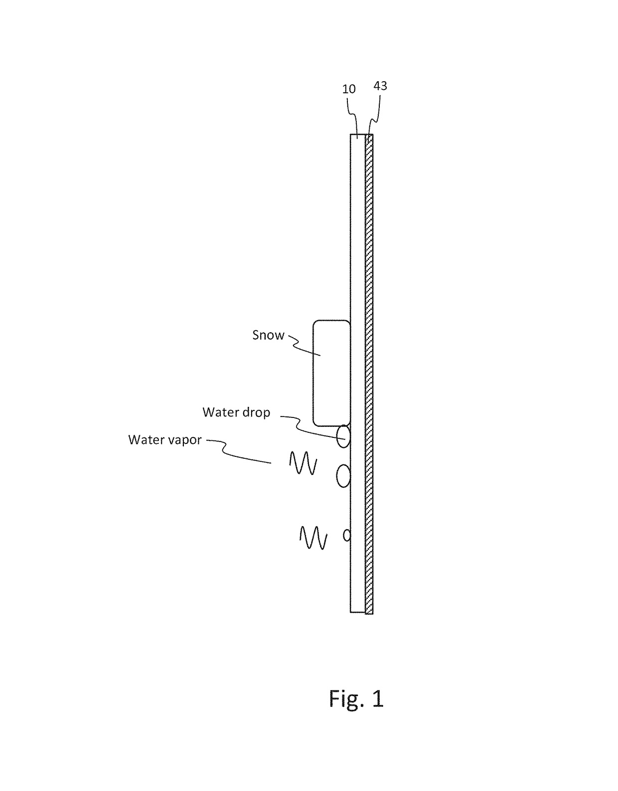
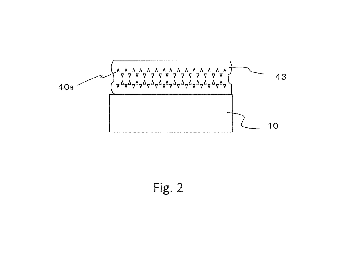
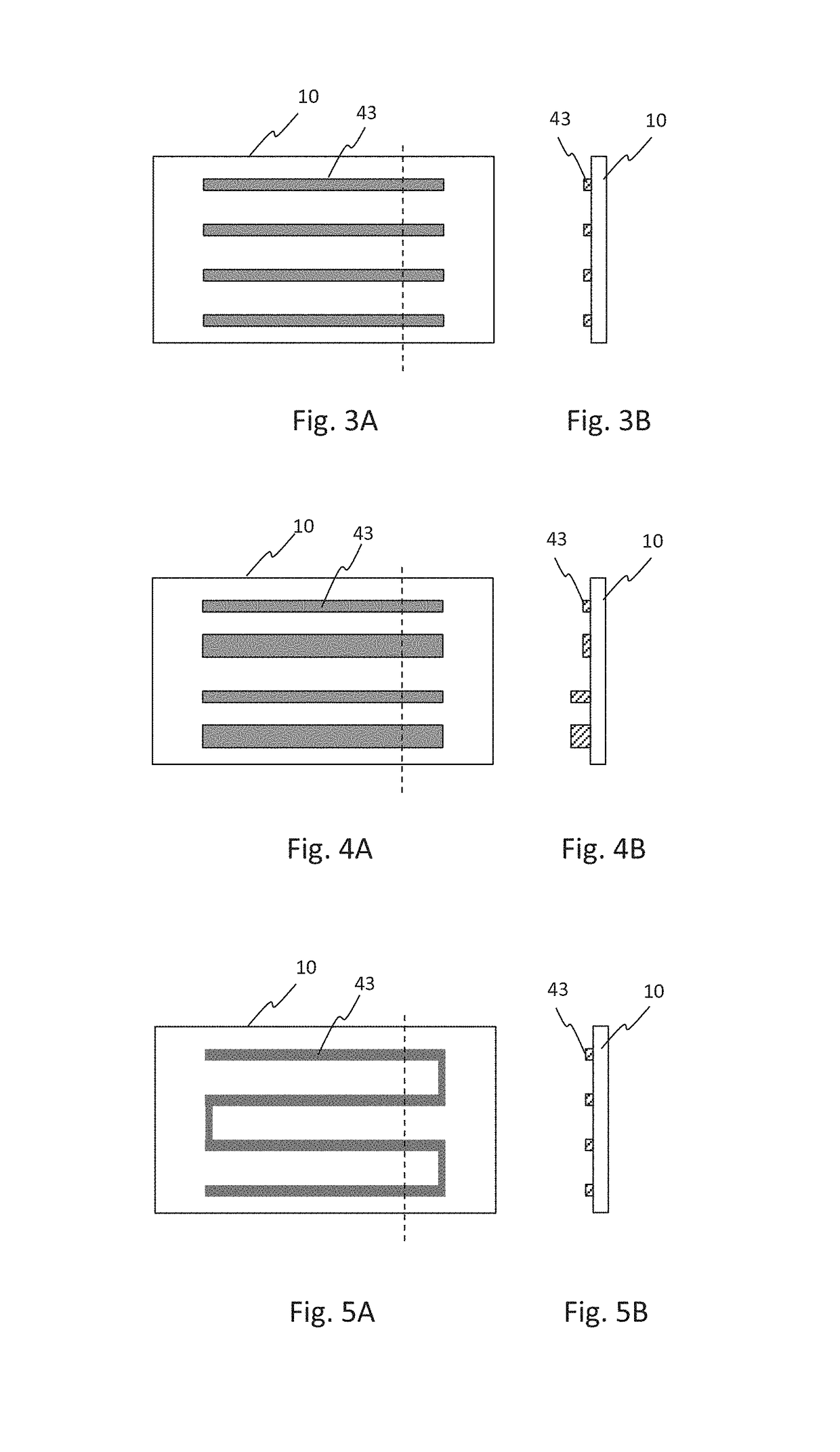
[0030]A sectional view of a light-transmitting substrate of this embodiment is shown as FIG. 1. As shown in FIG. 1, the light-transmitting substrate of this embodiment comprises and is constituted by a substrate 10 that transmits at least a light of a predetermined wavelength, and a conductor pattern 43 that is disposed on the substrate 10. The conductor pattern 43 generates heat to raise temperature of the surface of the substrate 10 when it is supplied with an electric current. According to this embodiment, the conductor ...

second embodiment

[0060]The light-transmitting substrate of the second embodiment will be explained.

[0061]In the light-transmitting substrate of the second embodiment, a light-emitting element 30 is mounted on the surface of the substrate 10 on which the conductor pattern 43 of the first embodiment is disposed, as shown in FIG. 10. The light-emitting element 30 is connected to the conductor pattern 43, supplied with an electric current via the conductor pattern, and emits light. The conductor pattern 43 itself generates heat, and also conducts heat generated by the light-emitting element 30 to raise temperature of a portion of the substrate 10 remote from the light-emitting element 30.

[0062]As shown in FIG. 10, the light-emitting element 30 can be disposed on the substrate 10 with a light-emitting surface thereof on the substrate 10 side to realize a structure that light emitted from the light-emitting surface is transmitted through the substrate 10 and projected to the outside. As a result, there ca...

third embodiment

[0074]The light-transmitting substrates of the first and second embodiments can be disposed on a display device, signal device, or illumination device so that the substrate constitutes the outermost surface. Snow and moisture adhering to these devices can be thereby, for example, evaporated. In these devices, the light-transmitting substrate is preferably disposed so that the surface opposite to the surface on which the conductor pattern 43 is disposed faces the outside.


PUM

PropertyMeasurementUnit
melting pointaaaaaaaaaa
temperatureaaaaaaaaaa
particle sizeaaaaaaaaaa

Abstract

A thin light-transmitting substrate showing high thermal conduction efficiency, and having a function of raising surface temperature thereof is provided.The light-transmitting substrate of the present invention comprises a substrate that transmits at least a light of a predetermined wavelength, and a conductor pattern that is disposed on the substrate, and generates heat to raise temperature of the surface of the substrate when it is supplied with an electric current. The conductor pattern is directly disposed on the substrate without any adhesive layer.

Description

TECHNICAL FIELD[0001]The present invention relates to a light-transmitting substrate having a function of raising surface temperature thereof.BACKGROUND ART[0002]Signs having a snow-melting function for preventing degradation of visibility of the signs due to adhesion of snow are disclosed in Patent document 1, and so forth. The sign disclosed in Patent document 1 has a structure that a snow-melting unit is disposed on a surface of an LED display comprising a plurality of LEDs disposed in the form of matrix. The surface of the LED display is covered with an acrylic resin plate. The snow-melting unit has a configuration that two of acrylic resin plates other than that of the LED display are facingly disposed with a metal frame between them, and a heater in the form of cord is disposed in the internal space, and the sign has a configuration that this snow-melting unit is adhered to the acrylic resin plate on the surface of the LED display. When the heater is electrified, air in the in...

Claims


Application Information

Patent Timeline
Patent Type & Authority Patents(United States)
IPC IPC(8): G09F7/00H05K1/03H05K1/16F21V33/00E04D13/10B60S1/02
CPCG09F7/002E04D13/103F21V33/00H05K1/0306H05K1/167H05K2201/10106H05K2201/0108H05K2201/0145H05K2201/0154H05K2201/0162B60S1/026G09F13/10H01L33/62H01L33/647F21Y2109/00
Inventor HANYA, AKIHIKOITO, KOSABUROABE, YOSHIYUKI
Owner STANLEY ELECTRIC CO LTD
Learn More