
Electronic candle

a technology of electronic candles and candles, applied in the field of electronic candles, can solve the problems of user's air blowing being blocked by the flame piece unable to enter the inner portion of the electronic candle, and user's effort being more to blow the air, so as to increase the accuracy of the air flow detection unit, create more space for the air, and effectively flow

Inactive Publication Date: 2019-01-10
FENG JUNJIE +1
View PDF2 Cites 2 Cited by
  • Summary
  • Abstract
  • Description
  • Claims
  • Application Information

AI Technical Summary

Benefits of technology

The present invention provides an electronic candle having a flame piece that can be easily lighted up and put out. The flame piece has edges that shrink towards the center portion to create more space for air to flow in, increasing the accuracy of air flow detection. The flame piece is designed to move in a natural way, simulating the real flame. The technical effects of this invention include improved sensory experience, easier operation, and increased safety.

Problems solved by technology

However, the piece to simulate candle flame in current electronic candles is cylindrical and is located axially from an inner portion of the electronic candle from an outer portion thereof, so the air blown by the user is blocked by the candle flame piece and cannot get into the inner portion of the electronic candle.
Thus, the user has to spend more effort to blow the air to put out the candle flame.

Method used


Image

  • Electronic candle
  • Electronic candle
  • Electronic candle

Examples


Embodiment Construction

[0015]The detailed description set forth below is intended as a description of the presently exemplary device provided in accordance with aspects of the present invention and is not intended to represent the only forms in which the present invention may be prepared or utilized. It is to be understood, rather, that the same or equivalent functions and components may be accomplished by different embodiments that are also intended to be encompassed within the spirit and scope of the invention.

[0016]Unless defined otherwise, all technical and scientific terms used herein have the same meaning as commonly understood to one of ordinary skill in the art to which this invention belongs. Although any methods, devices and materials similar or equivalent to those described can be used in the practice or testing of the invention, the exemplary methods, devices and materials are now described.

[0017]All publications mentioned are incorporated by reference for the purpose of describing and disclos...


PUM


Abstract

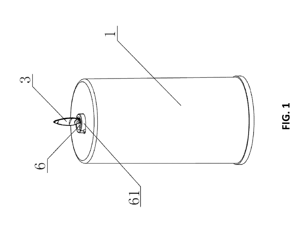
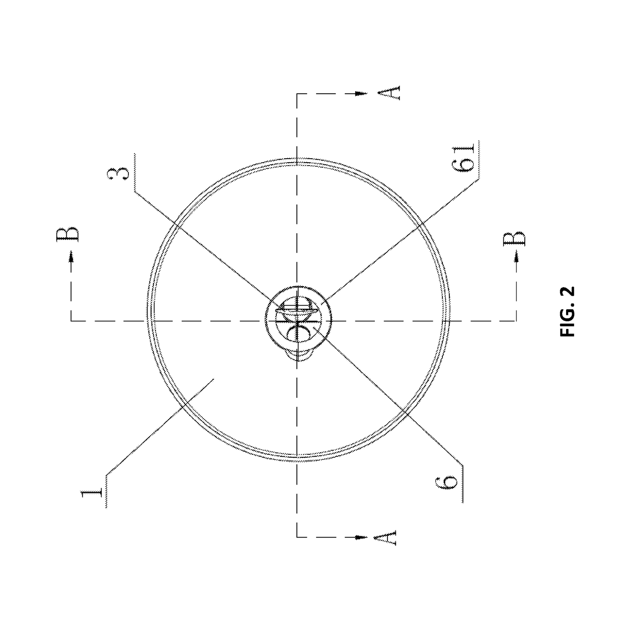
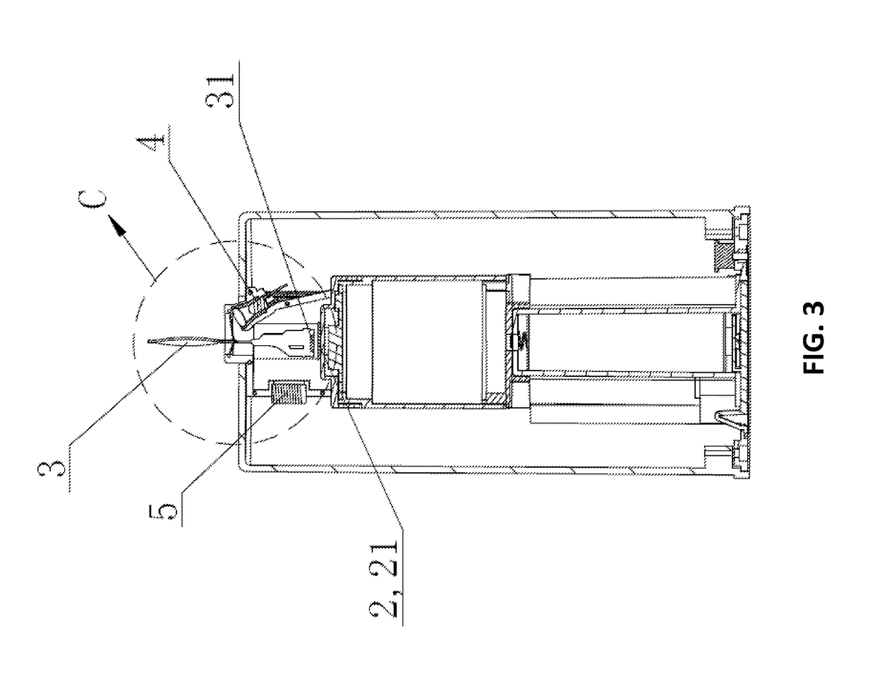
An electronic candle may include a main candle body, a signal processing module, a candle flame piece, a lighting unit to light up the candle flame piece and an air flow detecting unit, wherein the candle flame piece extends from a through hole from an inner portion of the main candle body to an outer portion thereof, and edges of the candle flame piece axially shrinks towards a center portion of the candle flame piece; the lighting unit is disposed below the candle flame piece to light up the candle flame piece; the air flow detecting unit is disposed at an inner portion of the electronic candle, and the air flow detecting unit and the lighting unit are both connected to the signal processing module.

Description

CROSS-REFERENCE TO RELATED APPLICATIONS[0001]This application claims priority under 35 U.S.C. § 119 (e) to U.S. Provisional Patent Application Ser. No. 62 / 530,789, filed on Jul. 10, 2017, the entire contents of which are hereby incorporated by reference.FIELD OF THE INVENTION[0002]The present invention relates to an electronic candle, and more particularly to an electronic candle that the flame thereof can be easily put out when the user blows air to it.BACKGROUND OF THE INVENTION[0003]Currently, most electronic candles can simulate real candle flame, and the flame can be put out when the user blows air to it. However, the piece to simulate candle flame in current electronic candles is cylindrical and is located axially from an inner portion of the electronic candle from an outer portion thereof, so the air blown by the user is blocked by the candle flame piece and cannot get into the inner portion of the electronic candle. Thus, the user has to spend more effort to blow the air to ...

Claims


Application Information

Patent Timeline
Patent Type & Authority Applications(United States)
IPC IPC(8): H05B37/02F21V23/04H05B33/08F21S10/04F21S6/00H05B44/00
CPCH05B37/0227F21V23/0485H05B33/0854F21Y2115/10F21S6/001F21W2121/00F21S10/046H05B47/105H05B45/18
Inventor FENG, JUNJIEFENG, JIANLIANG
Owner FENG JUNJIE
Learn More