Current sensor and current sensor module
- Summary
- Abstract
- Description
- Claims
- Application Information
AI Technical Summary
Benefits of technology
Problems solved by technology
Method used
Image

Examples
first preferred embodiment
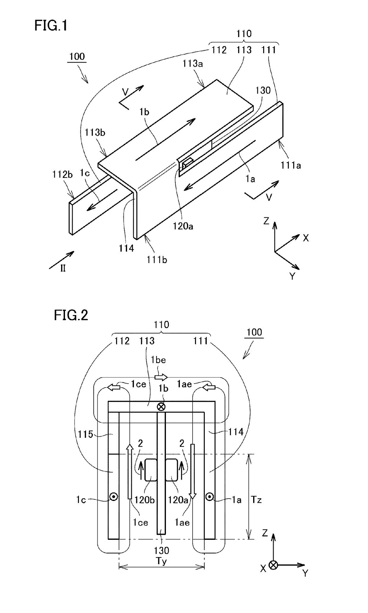
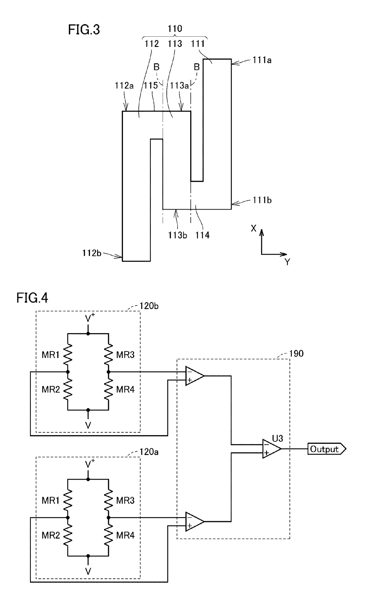
[0067]FIG. 1 is a perspective view illustrating the external appearance of a current sensor according to a first preferred embodiment of the present invention. FIG. 2 is a front view of the current sensor in FIG. 1, viewed from the direction of an arrow II. FIG. 3 is a developed view illustrating the shape of a conductor in the current sensor according to the first preferred embodiment of the present invention, before the conductor is folded. FIG. 4 is a circuit diagram illustrating the circuit configuration of the current sensor according to the first preferred embodiment of the present invention. The length direction of the conductor is indicated as the X-axis direction, the width direction of the conductor is indicated as the Y-axis direction, and the height direction of the conductor is indicated as the Z-axis direction in FIG. 1 to FIG. 3.
[0068]As illustrated in FIG. 1 to FIG. 3, a current sensor 100 according to the first preferred embodiment of the present invention includes ...
second preferred embodiment
[0119]A current sensor according to a second preferred embodiment of the present invention will now be described. Since a current sensor 200 according to the second preferred embodiment differs from the current sensor 100 according to the first preferred embodiment mainly in the orientation of the substrate and the orientation of the detection axis of each of the first magnetic sensor and the second magnetic sensor with respect to the main surface of the substrate, the same reference numerals are used in the current sensor 200 according to the second preferred embodiment to identify the same or similar components in the current sensor 100 according to the first preferred embodiment and a duplicated description of such components is omitted herein.
[0120]FIG. 7 is a front view illustrating the configuration of the current sensor according to the second preferred embodiment of the present invention. A state in which the current sensor 200 is viewed from the same direction as in FIG. 2 ...
third preferred embodiment
[0127]A current sensor according to a third preferred embodiment of the present invention will now be described. Since a current sensor 300 according to the third preferred embodiment differs from the current sensor 100 according to the first preferred embodiment only in that the substrate is housed in a housing, the same reference numerals are used in the current sensor 300 according to the third preferred embodiment to identify the same or similar components in the current sensor 100 according to the first preferred embodiment and a duplicated description of such components is omitted herein.
[0128]FIG. 8 is a perspective view illustrating the external appearance of the current sensor according to the third preferred embodiment of the present invention. As illustrated in FIG. 8, the current sensor 300 according to the third preferred embodiment of the present invention further includes a housing 350 in which the substrate 130 including the first magnetic sensor 120a and the second ...
PUM
 Abstract
Description
Claims
Application Information
 - R&D Engineer
- R&D Manager
- IP Professional
- Industry Leading Data Capabilities
- Powerful AI technology
- Patent DNA Extraction
Browse by: Latest US Patents, China's latest patents, Technical Efficacy Thesaurus, Application Domain, Technology Topic.
© 2024 PatSnap. All rights reserved.Legal|Privacy policy|Modern Slavery Act Transparency Statement|Sitemap