Image forming apparatus

a technology of image forming apparatus and forming sheet, which is applied in the direction of electrographic process apparatus, instruments, optics, etc., can solve the problems of misregistration of an image formed on the sheet, decrease of the outside diameter, etc., and achieve the effect of reducing the misregistration of an image transferred

Inactive Publication Date: 2019-01-17
CANON KK
View PDF0 Cites 2 Cited by
  • Summary
  • Abstract
  • Description
  • Claims
  • Application Information

AI Technical Summary

Benefits of technology

[0007]The present disclosure provides an image forming apparatus that controls the speed at which a conveying unit conveys a printing material toward a transfer unit to reduce misregistration of an image transferred to the printing material.

Problems solved by technology

In other words, the registration roller pair is worn out due to long use, so that the outside diameter decreases.
The change in the actual sheet conveying speed of the registration roller pair makes it difficult to keep synchronization with the image formed on the image bearing member, causing misregistration of an image formed on the sheet.

Method used


Image

  • Image forming apparatus
  • Image forming apparatus
  • Image forming apparatus

Examples


first embodiment

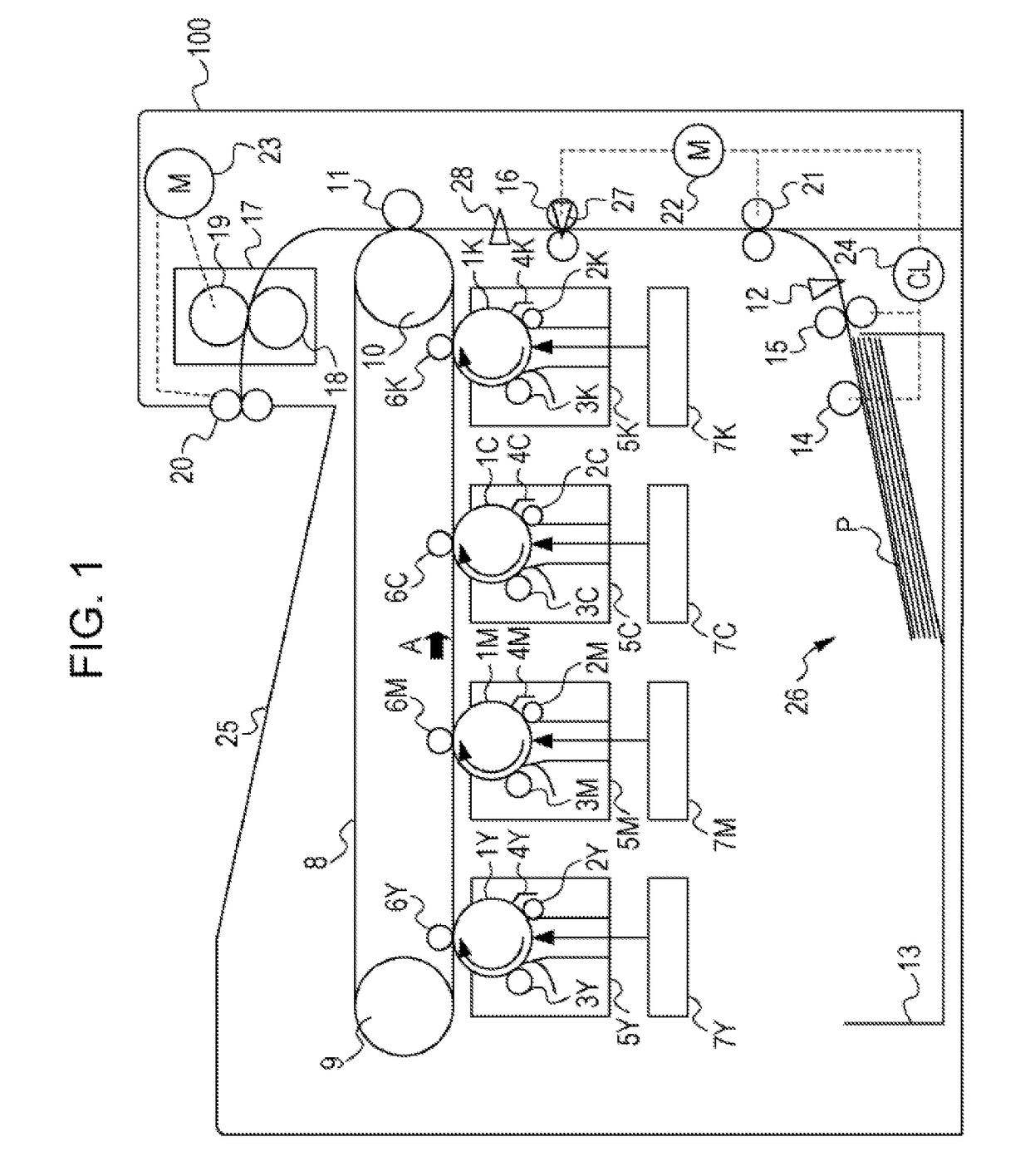
[0017]In the present embodiment, an electrophotographic laser beam printer 100 (hereinafter referred to as “printer 100”) will be described as the image forming apparatus. The printer 100 illustrated in FIG. 1 forms a color image on a sheet of paper P (a printing material).

Image Forming Unit

[0018]The printer 100 includes process cartridges 5Y, 5M, 5C, and 5K which are detachable from the main body (also referred to as “casing”). The four process cartridges 5Y, 5M, 5C, and 5K have the same structure but differ in that they form an image with a yellow (Y), magenta (M), cyan (C), or black (K) toner. Thus, in FIG. 1, a member of a specific color represented by attaching one of signs indicating the colors (Y, M, C, and K) to a sign corresponding to the member. In the case where there is no need to specify a member of a specific color, the signs representing the colors (Y, M, C, and K) will be omitted hereinbelow.

[0019]The process cartridges 5 each include a photosensitive drum 1 serving ...

second embodiment

[0069]In the present embodiment, a method for detecting that the aging wear of the registration roller 16 has advanced, so that the performance of the printer 100 cannot be fulfilled, that is, the life has expired, and a method for detecting that the registration roller 16 has been replaced will be described. Since main points are the same as in the first embodiment, only differences from the first embodiment will be described.

Detecting Life of Registration Roller 16 Due to Change in Estimated Diameter

[0070]The diameter of the registration roller 16 gradually decreases due to aging wear from the beginning of the life of the printer 100 to the end of the life. In other words, when the estimated diameter becomes less than the diameter at the end of estimated design life, it can be determined that the life of the registration roller 16 has expired.

Detecting Replacement of Registration Roller 16 Due to Change in Estimated Diameter

[0071]When the life of the registration roller 16 ends, t...


PUM


Abstract

An image forming apparatus includes a conveying unit, transfer unit, a loop detecting unit, a driving source, a control unit, and a measuring unit. The transfer unit transfers an image formed on an image bearing member to the printing material conveyed by the conveying unit driven by the driving source. The loop detecting unit detects an amount of a loop formed in the printing material between the conveying and transfer units. The control unit changes a rotational speed of the driving source based on the detection result. The measuring unit measures a rotation amount of the driving source while a first printing material is conveyed by both of the conveying and transfer units. The control unit controls the rotational speed of the driving source based on the measured rotation amount so that a leading end of a second printing material reaches the transfer unit per the image bearing member image.

Description

BACKGROUND OF THE INVENTIONField of the Invention[0001]The present disclosure relates to image forming apparatuses, such as copiers and printers.Description of the Related Art[0002]For image forming apparatuses such as copiers and printers, loop control for detecting the degree of a loop formed in a sheet between two conveying units and changing the speed of the sheet conveyed by the conveying units according to the detected degree (loop amount).[0003]Japanese Patent Laid-Open No. 1-176746 discloses control of the degree of a loop between a registration roller pair for synchronously conveying a sheet and an image forming unit. The image forming apparatus disclosed in Japanese Patent Laid-Open No. 1-176746 increases the speed at which the sheet is conveyed by the registration roller pair upon determining that the degree of a loop formed in the sheet between the registration roller pair and the image forming unit is low. Upon determining that the degree of the loop formed in the sheet...

Claims


Application Information

Patent Timeline
Patent Type & Authority Applications(United States)
IPC IPC(8): G03G15/00
CPCG03G15/6529G03G15/6564G03G15/55
Inventor SUGIYAMA, YUKISUZUKI, MASATOYOSHIKAWA, NAOKI
Owner CANON KK
Why Eureka
Try Eureka