Assist grip handle

Active Publication Date: 2019-01-24
HONDA ACCESS CORP
View PDF0 Cites 0 Cited by
  • Summary
  • Abstract
  • Description
  • Claims
  • Application Information

AI Technical Summary

Benefits of technology

[0025]According to the configuration as set forth in the first aspect, the escape hammer can be stored in the assist grip handle in a compact manner.
[0026]According to the configuration as set forth in the second aspect, the attachment and removal of the hammer is easy.
[0027]According to the configuration as set forth in the third aspect, since a part of the hammer composes a part of the assist grip handle, the hammer is allowed to have a large size.
[0028]According to the

Problems solved by technology

However, with regard to the above emergency escape tool, if there are used multiple hammers, there will also be required multiple sections dedicated to storing the multiple hammers, which is unfavorable in the case of, for example, a vehicle with a limited inner

Method used


Image

  • Assist grip handle
  • Assist grip handle
  • Assist grip handle

Examples


first embodiment

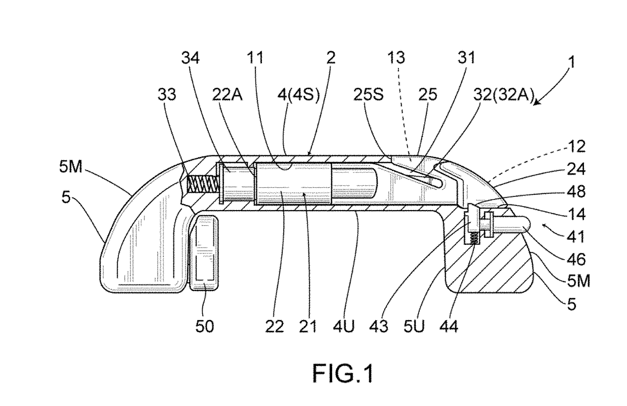
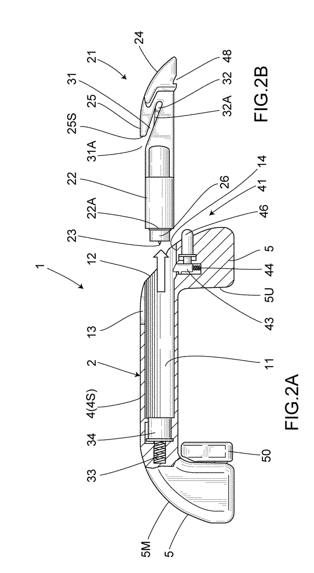
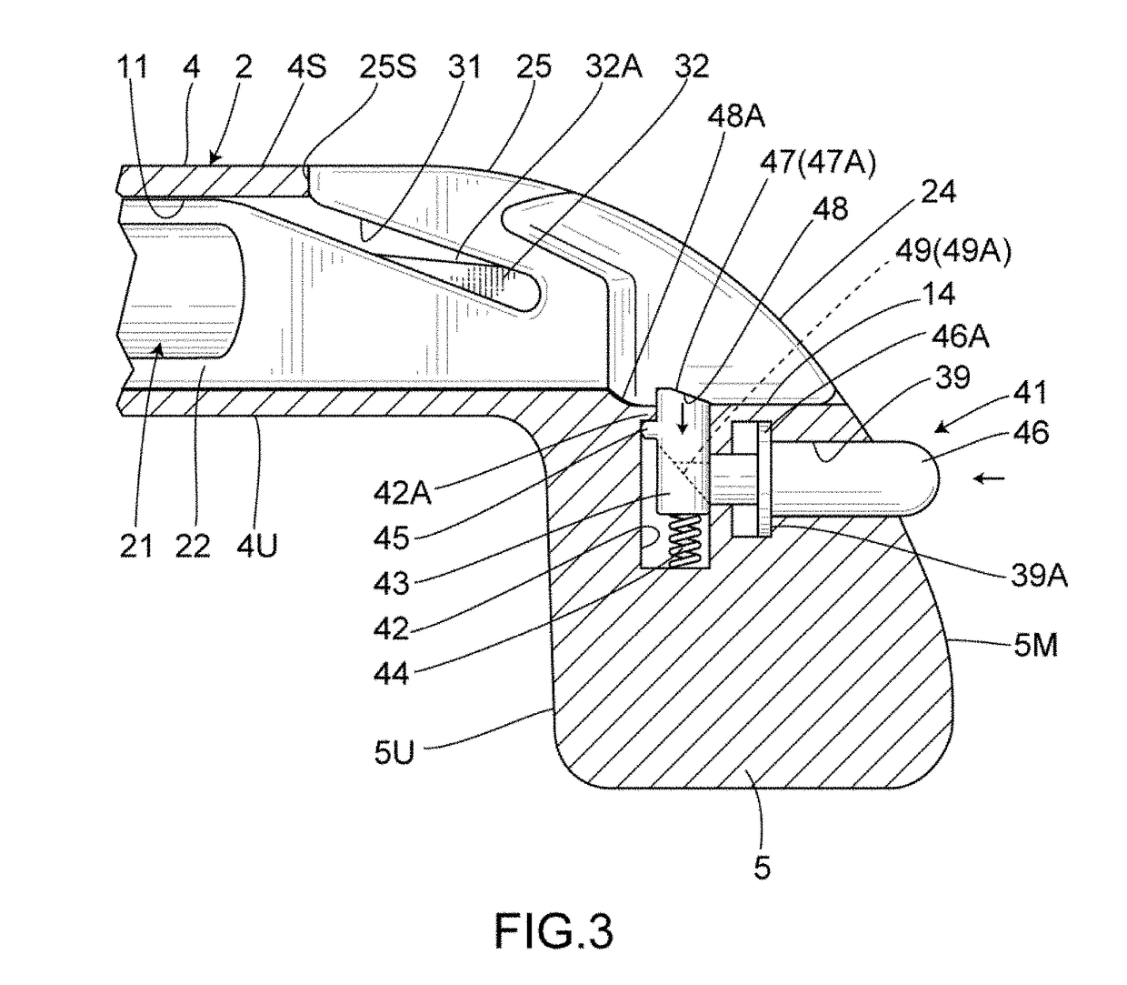
[0057]FIGS. 1 to 6 show a first embodiment of the invention. As shown in these drawings, an assist grip handle 1 integrally includes a main body 2 and an attachment portion(s) 3. The main body 2 is made of a synthetic resin; and includes a grip portion 4 extending in the shape of a bar, and curved portions 5, 5 as bent portions integrally provided at the two ends of such grip portion 4 in a length direction. Further, the attachment portions 3, 3 are respectively provided at the curved portions 5, 5, and the attachment portion 3 is to be attached to an interior member 6 of a vehicle. Particularly, the attachment portion 3 is provided at a back surface side of the curved portion 5.

[0058]Further, a storage portion 11 is formed in the grip portion 4. This storage portion 11 is formed along the length direction of the grip portion 4, and has an opening section 12 that is open at one of the curved portions 5.

[0059]The interior member 6 may, for example, be an inner wall portion in the int...

second embodiment

[0092]FIGS. 8 and 9 show a second embodiment of the present invention. Parts identical to those in the first embodiment are given identical symbols, and the detailed descriptions thereof are thus omitted. The escape hammer 21 in this embodiment is that of a type allowing the punch 23 to protrude when an operation portion not shown has been pushed or manipulated in other ways. Further, a pressing body 61 is provided at the coil spring 33 as the biasing member, and this pressing body 61 is capable of pushing the tip end surface 22A of the hammer grip portion 22.

[0093]Further, there is provided a regulation operation portion 62 serving as both the regulation portion and the operation portion. This regulation operation portion 62 is composed of a ring body 63 fixed to the opening section 12 side; and a cap-shaped blocking member 64 that is detachably provided at the ring body 63 and serves to block the opening section 12. This blocking member 64 includes a ring part 64A to be fitted ont...

third embodiment

[0098]FIGS. 10 to 12 show a third embodiment of the present invention. Parts identical to those in the above embodiments are given identical symbols, and the detailed descriptions thereof are thus omitted. In this embodiment, a regulation portion is provided at the bottom portion side of the storage portion 11 that is located on the opposite side of the opening section 12; and an operation portion is provided at the opening section 12 side.

[0099]The regulation portion in this embodiment is a push latch 91. This push latch 91 includes a locking main body 92 fixed to the bottom portion of the storage portion 11; and a locking storage portion 93 that is engageable with the locking main body 92 and is provided at the tip end side of the hammer grip portion 22. As a result of inserting the hammer 21 into the storage portion 11, once the locking storage portion 93 at the tip end has pushed the locking main body 92, the locking main body 92 will be locked to the locking storage portion 93 ...


PUM


Abstract

Provided is an assist grip handle storing an escape hammer. The handle is to be attached to an interior space of a vehicle, and includes a bar-shaped grip portion; a curved portion continuous with at least one end of the grip portion; and an attachment portion continuous with the curved portion and attached to an interior member of the vehicle. Since provided inside the grip portion is a storage portion continuous with an opening section formed at the curved portion side, and an escape hammer is stored in the storage portion, the hammer can be stored in the handle in a compact manner. Since there are provided a biasing member biasing the hammer toward the opening section side; a regulation portion for regulating the hammer; and a push button for releasing the restriction by the regulation portion, the hammer can be easily installed in and removed from the handle.

Description

TECHNICAL FIELD[0001]The present invention relates to an assist grip handle equipped with a hammer used to break a window glass.BACKGROUND ART[0002]Conventionally, as such a type of assist grip handle, there has been known a hammer-equipped assist grip handle (e.g. Patent document 1) including a grip portion having the shape of a band whose central region is curved in a concave manner; a hammer member(s) vertically provided at both ends of the grip portion, and capable of being used to break a window glass of a vehicle in which the assist grip handle is installed; a receiving member(s) that is to be embedded and fixed in an inner side of a roof side of the vehicle in which the assist grip handle is to be installed, has an insertion hole allowing the hammer member to be inserted therethrough, whereby the hammer member as well as the grip portion may then be removed from such insertion hole; and a switching unit for switching between a state prohibiting the disengagement of the hammer...

Claims


Application Information

Patent Timeline
IPC IPC(8): B60N3/02B25D1/00
CPCB60N3/026B25D1/00B60N3/023B25D2250/271B25D2250/295B60N3/02A62B3/005
Inventor TAKENAKA, SHINPEISAITO, AKIHIKO
Owner HONDA ACCESS CORP
Why Eureka
Try Eureka