Catalytic converter and method for manufacturing casing

a catalytic converter and manufacturing method technology, applied in the field of catalytic converters, can solve the problems of complicated troublesome work in order to correct the deformation, difficult to form the major arc-shaped parts, and complicated adjustment of the peripheral length

Active Publication Date: 2019-01-24
YUTAKA GIKEN CO LTD +1
View PDF2 Cites 0 Cited by
  • Summary
  • Abstract
  • Description
  • Claims
  • Application Information

AI Technical Summary

Benefits of technology

[0005]The present invention has been accomplished in light of such circumstances, and it is an object thereof to provide a catalytic converter capable of suppressing a press load, when press-forming a reduced diameter tubular part of a casing, from becoming large and unequal in a peripheral direction of the reduced diameter tubular part, and also to provide a method for manufacturing the casing, in which the casing can be manufactured appropriately.

Problems solved by technology

Therefore, a press load in one direction for forming the single flat part acts on the reduced diameter tubular part, and this results in unequal loads acting in a peripheral direction of the reduced diameter tubular part, which may deform opposite end portions of the casing in their spreading direction, thereby requiring complicated troublesome work in order to correct the deformation.
However, there are problems that it is difficult to form the major arc-shaped parts and the adjustment of the peripheral length becomes complicated.

Method used


Image

  • Catalytic converter and method for manufacturing casing
  • Catalytic converter and method for manufacturing casing
  • Catalytic converter and method for manufacturing casing

Examples


first embodiment

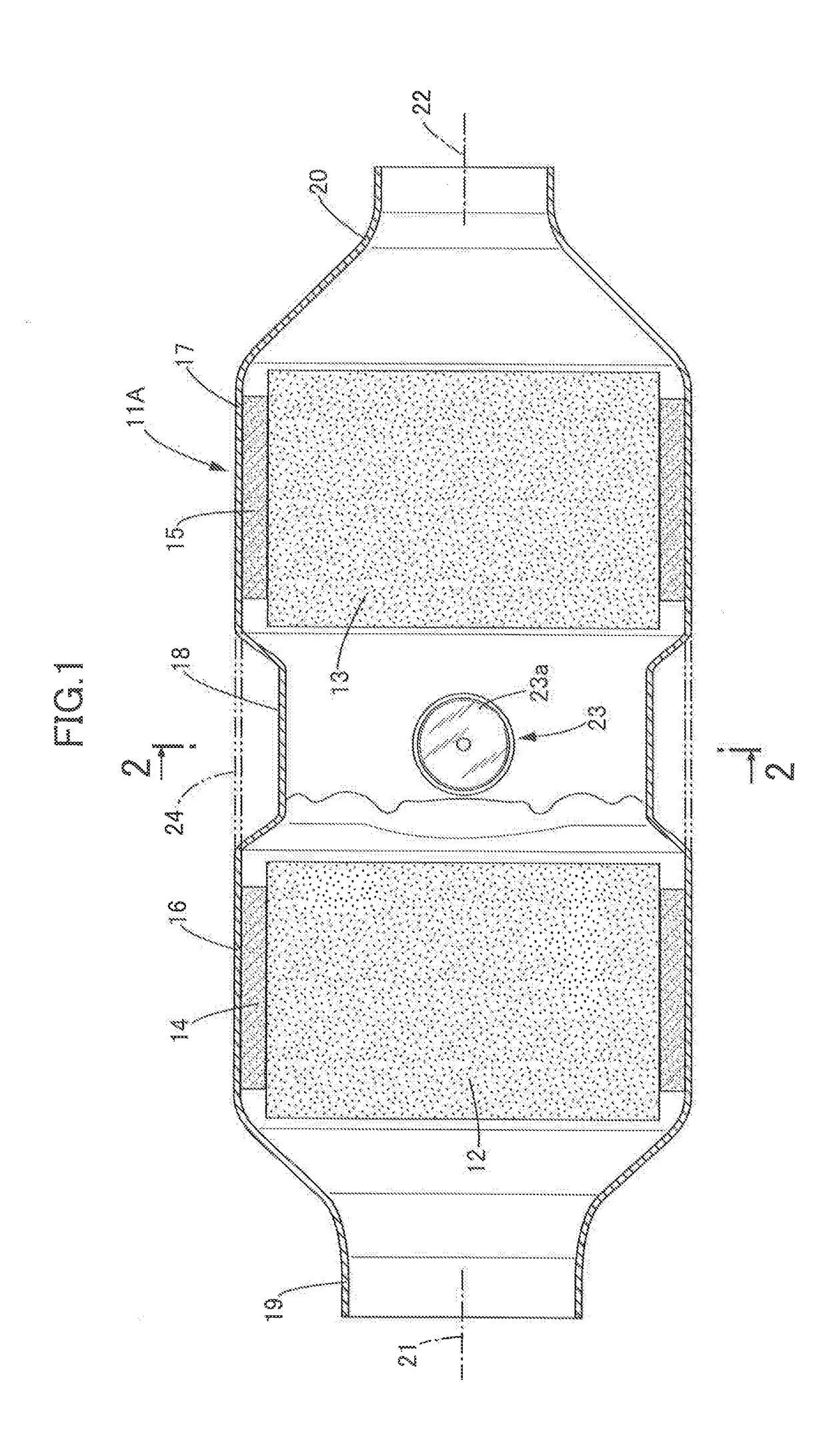
[0033]the present invention is now explained referring to FIGS. 1 to 4. First, in FIG. 1, a catalytic converter includes a tubular, for example, cylindrical casing 11A and a plurality of, for example, two monolithic catalyst carriers 12 and 13 that are accommodated in series inside the casing 11A so as to be separated from each other in a direction along an axis of the casing 11A, elastic mats 14 and 15 as holding materials being respectively wound around outer peripheries of the monolithic catalyst carriers 12 and 13.

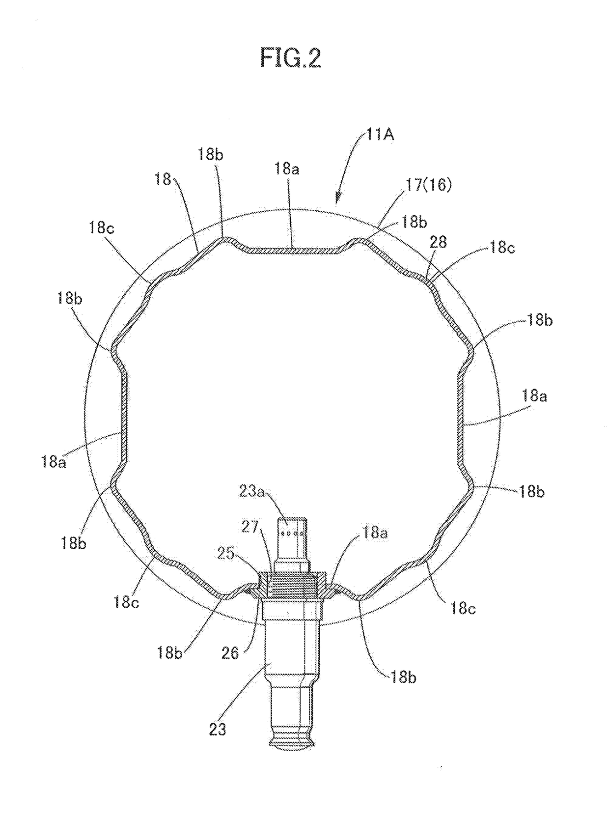
[0034]The casing 11A is formed so as to integrally include at least one pair of (a pair of, in this embodiment) holding tubular parts 16 and 17, a reduced diameter tubular part 18 integrally connecting the holding tubular parts 16 and 17 to each other, and a pair of funnel-shaped connecting tubular parts 19 and 20 respectively connected to end portions, on sides opposite to the reduced diameter tubular part 18, of the pair of holding tubular parts 16 and 17.

[0035]The m...

second embodiment

[0051]A reduced diameter tubular part 32 of a casing 11B is obtained by press-forming a portion, between holding tubular parts 16 and 17, of a casing material 24 of a tubular shape that corresponds to that of the holding tubular parts 16 and 17. Flat parts 32a are formed respectively in a plurality of, three in this second embodiment, places at equal intervals in the peripheral direction of the reduced diameter tubular part 32. An O2 sensor 23 is attached to one of these flat parts 32a.

[0052]First protrusions or ribs 32b are respectively formed on opposite end portions, along a peripheral direction of the reduced diameter tubular part 32, of each of the flat parts 32a, the first protrusions 32b protruding outward of the reduced diameter tubular part 32 and extending in an axial direction thereof. Moreover, second protrusions or ribs 32c are each formed on an outer surface of the reduced diameter tubular part 32 at a central portion in the peripheral direction between each adjacent ...

third embodiment

[0055]A reduced diameter tubular part 33 of a casing 11C is obtained by press-forming a portion, between holding tubular parts 16 and 17, of a casing material 24 of a tubular shape that corresponds to that of the holding tubular parts 16 and 17. Flat parts 33a are formed respectively in a plurality of, two in this third embodiment, places at intervals in a peripheral direction of the reduced diameter tubular part 33.

[0056]These flat parts 33a are formed in the reduced diameter tubular part 33 so as to extend along a pair of imaginary planes 34 and 35 orthogonal to each other. An O2 sensor 23 is attached to one of these flat parts 33a.

[0057]First protrusions or ribs 33b protruding outward of the reduced diameter tubular part 33 and extending in an axial direction thereof are respectively formed on opposite end portions, along the peripheral direction of the reduced diameter tubular part 33, of each of the flat parts 33a. Second protrusions or ribs 33c protruding outward of the reduc...


PUM

PropertyMeasurementUnit
diameteraaaaaaaaaa
electric resistanceaaaaaaaaaa
lengthaaaaaaaaaa

Abstract

A catalytic converter includes: a tubular casing including at least a pair of holding tubular parts and a reduced diameter tubular part that integrally connects the holding tubular parts to each other; and a monolithic catalyst carrier accommodated in each of the holding tubular parts, the reduced diameter tubular part being obtained by press-forming a portion, between the holding tubular parts, of a casing material of a tubular shape that corresponds to that of the holding tubular parts. Flat parts are formed respectively in a plurality of places at intervals in a peripheral direction of the reduced diameter tubular part, a sensor being attached to at least one of the flat parts. Accordingly, a press load when press-forming the reduced diameter tubular part is suppressed from becoming large and unequal in the peripheral direction of the reduced diameter tubular part.

Description

BACKGROUND OF THE INVENTIONField of the Invention[0001]The present invention relates to a catalytic converter comprising: a tubular casing including at least a pair of holding tubular parts and a reduced diameter tubular part that integrally connects the holding tubular parts to each other; and a monolithic catalyst carrier accommodated in each of the holding tubular parts, the reduced diameter tubular part being obtained by press-forming a portion, between the holding tubular parts, of a casing material of a tubular shape that corresponds to that of the holding tubular parts. The present invention also relates to a method for manufacturing the casing.Description of the Related Art[0002]Such a catalytic converter is known in, for example, Japanese Patent Application Laid-open No. 2004-92461 and Japanese Patent Application Laid-open No. 2012-117443.[0003]In a catalytic converter disclosed in the above-described Japanese Patent Application Laid-open No. 2004-92461, a single flat part ...

Claims


Application Information

Patent Timeline
Patent Type & Authority Applications(United States)
IPC IPC(8): F01N3/28B21D15/02B21D53/88F01N13/00
CPCF01N2450/20F01N2450/22F01N3/2803B21D15/02B21D53/88F01N13/008F01N3/2842F01N13/0093F01N13/1872F01N13/0097
Inventor TAKAYANAGI, JUNOOKA, TOSHIHIROYAMAMOTO, NORITAKAISHII, KAZUMASAHATAKEYAMA, YOSHIAKI
Owner YUTAKA GIKEN CO LTD
Why Eureka
Try Eureka