
Holographic recording medium and method of manufacturing holographic recording medium

a technology manufacturing method, which is applied in the field of holographic recording medium, can solve the problems of extremely limited material choice range and extreme limit of material choi

Inactive Publication Date: 2008-11-20
FUJIFILM CORP
View PDF3 Cites 0 Cited by
  • Summary
  • Abstract
  • Description
  • Claims
  • Application Information

AI Technical Summary

Benefits of technology

[0010]With this construction of the present invention, since the recording layer and at least one adjacent layer are attached with adhesive, these layers may be separately molded and cured in advance. This makes it possible to freely choose materials for the recording layer composition unlike in the case of the conventional methods in which materials for the photosensitive resin solution are chosen on the basis of various conditions such as viscosity, curing process time, etc.
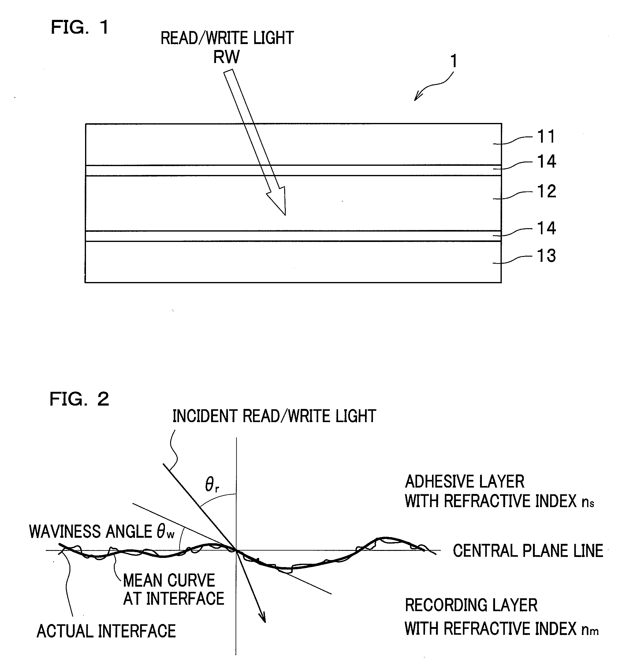
[0013]This holographic recording medium allows the refractive index ns of the adhesive layer and the refractive index nm of the recording layer to be determined based on various parameters affecting reflection and scattering of light at the interface between the adhesive layer and the recording layer. Therefore, it is possible to prevent reflection and scattering of light at the interface.
[0014]In the aforementioned holographic recording medium, a surface roughness Ra relative to a mean curve obtained at an interface between the recording layer and the adhesive layer may be in the range of 5-90 nm. According to this holographic recording medium, even in the case where the surface roughness causes reflection / scattering of light (i.e., the period from peak to valley is exceptional), it is possible to prevent reflection / scattering of light.
[0020]According to the present invention, the recording layer and at least one adjacent layer can be separately prepared and cured in advance, followed by attaching these layers with adhesive. Therefore, it is possible to offer an extended range of material choice for the recording layer composition.

Problems solved by technology

However, in principle, these conventional methods require to cure the photosensitive resin solution after injecting or charging the same into the hollow portion.
This restriction disadvantageously leads to an extremely limited range of material choice for the photosensitive resin solution (recording layer composition).
Accordingly, the range of material choice is extremely limited.

Method used


Image

  • Holographic recording medium and method of manufacturing holographic recording medium
  • Holographic recording medium and method of manufacturing holographic recording medium

Examples


Embodiment Construction

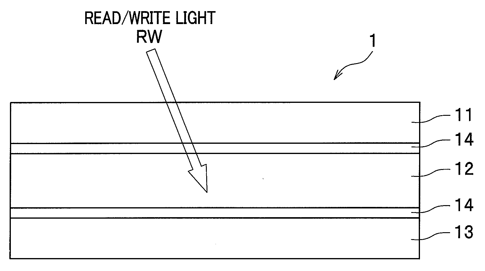
[0024]With reference to the accompanying drawings, one preferred embodiment of the present invention will be described below.

[0025]As shown in FIG. 1, a holographic recording medium 1 includes a cover layer 11, a recording layer 12, and a bottom substrate 13. The recording layer 12 is attached to the cover layer 11 and the bottom substrate 13 that are adjacent to the recording layer 12, via adhesive layers 14, 14.

[0026]The cover layer 11 is a layer for protecting the upper surface of the recording layer 12. The cover layer 11 is made of a material which allows transmission of read / write light RW whose wave length is approximately 532 nm, for example. Herein, the term “read / write light RW” indicates either one of information light, reference light, and reading light. Any known materials may be used for the cover layer 11 as long as they are sufficiently transparent in the wavelength range of the light used. For example, the cover layer 11 is made of a material such as glass, ceramic,...


PUM

PropertyMeasurementUnit
surface roughness Raaaaaaaaaaa
surface roughnessaaaaaaaaaa
refractive indexaaaaaaaaaa

Abstract

A holographic recording medium with a plurality of layers including a recording layer, on which are recorded interference patterns generated by interference of information light and reference light. The recording layer is attached to at least one adjacent layer with adhesive.

Description

CROSS REFERENCE TO RELATED APPLICATIONS[0001]This application claims the foreign priority benefit under Title 35, United States Code, §119(a)-(d) of Japanese Patent Application No. 2007-035667 filed on Feb. 16, 2007 in the Japan Patent Office, the disclosure of which is herein incorporated by reference in its entirety.BACKGROUND OF THE INVENTION[0002]The present invention relates to a holographic recording medium on which data is recorded using interference of light waves, and a method of manufacturing such a holographic recording medium.[0003]In recent years, development has been carried out for holographic recording media with a recording layer in the shape of a thick film, on which an extremely large number of data is recorded as interference patterns using interference of light waves. The following two manufacturing methods have been conventionally and mainly known as manufacturing methods for such holographic recording media.[0004]According to the first conventional method such...

Claims


Application Information

Patent Timeline
Patent Type & Authority Applications(United States)
IPC IPC(8): G03H1/02B32B37/00
CPCG03H1/0248G03H1/0256G03H2240/50G03H2240/54G03H2250/10G03H2250/35
Inventor KAMO, MAKOTO
Owner FUJIFILM CORP
Learn More