
Adjustment method of shaping device

a technology of shaping device and adjustment method, which is applied in the field of adjustment method of shaping device, can solve the problems of inability to manufacture a shaped object of an appropriate shape, inability to properly set the amount of ink ejection by the nozzle row, and the inability to accurately manufacture a shaped object, etc., to achieve the effect of reliably preventing contact between the inkjet head and the ink receiving container and easy installation

Inactive Publication Date: 2019-12-26
MIMAKI ENG
View PDF0 Cites 0 Cited by
  • Summary
  • Abstract
  • Description
  • Claims
  • Application Information

AI Technical Summary

Benefits of technology

The adjustment method of the shaping device described in this patent allows for the proper control of the amount of ink ejected from the inkjet head. This is achieved by measuring the weight of the ink and adjusting the shaping device accordingly. This method results in the production of precise and shaped objects through the control of the ink ejection process.

Problems solved by technology

Therefore, in this shaping device, it is difficult to manufacture a shaped object of an appropriate shape unless the amount of ink ejected by the inkjet head is appropriately controlled.
Therefore, in this embodiment, although the amount of ink ejected by the nozzle row is corrected in the ink ejection amount correction process, the amount of ink ejected by the nozzle row in the ink ejection process after the ink ejection amount correction process may not become the ejection amount corresponding to the correction in the ink ejection amount correction process, and the amount of ink ejected by the nozzle row may not be appropriately set in the ink ejection amount setting process.
Therefore, the ejection amount of ink in the ink ejection process before the determination process and the ejection amount of ink in the ink ejection process after the determination process change, and the amount of ink ejected by the nozzle row may not be appropriately set in the ink ejection amount setting process.

Method used


Image

  • Adjustment method of shaping device
  • Adjustment method of shaping device
  • Adjustment method of shaping device

Examples


Embodiment Construction

[0035]Hereinafter, an embodiment of the present disclosure will be described with reference to the accompanying drawings.

Schematic Configuration of Shaping Device

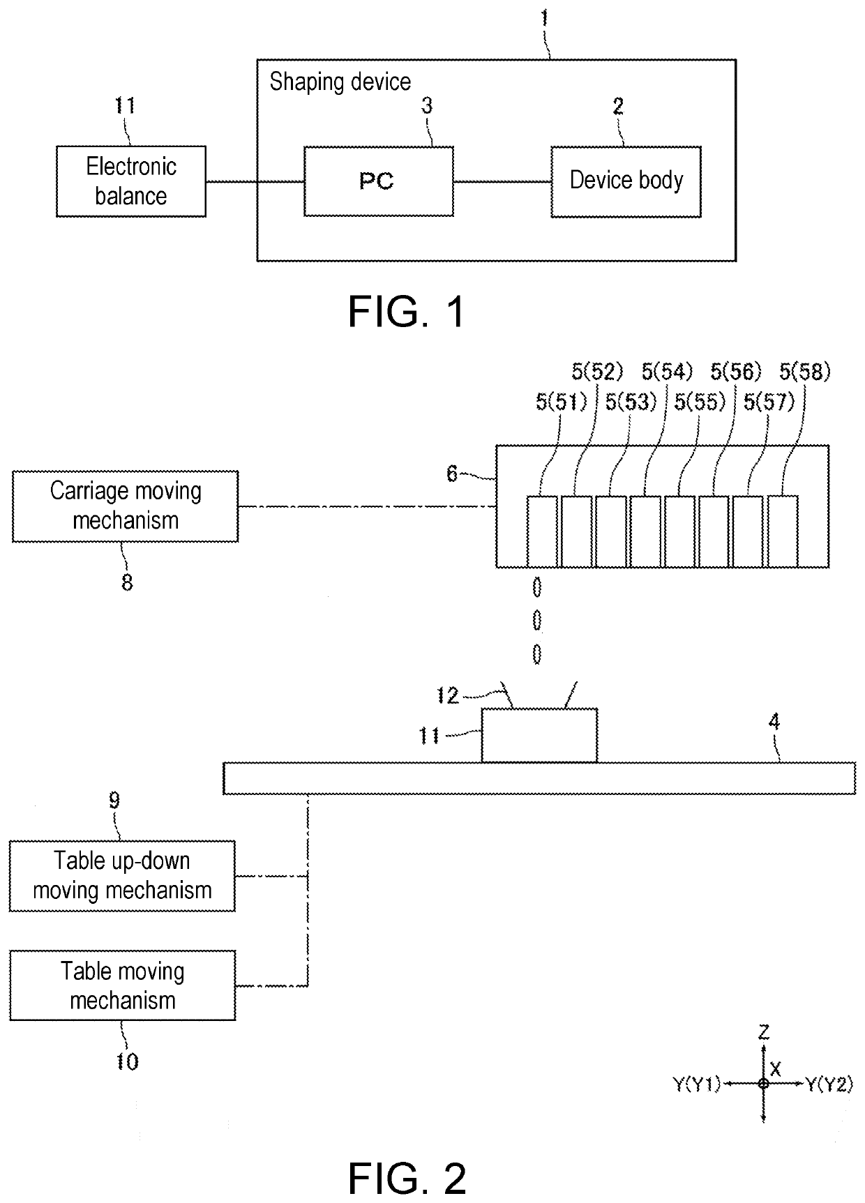
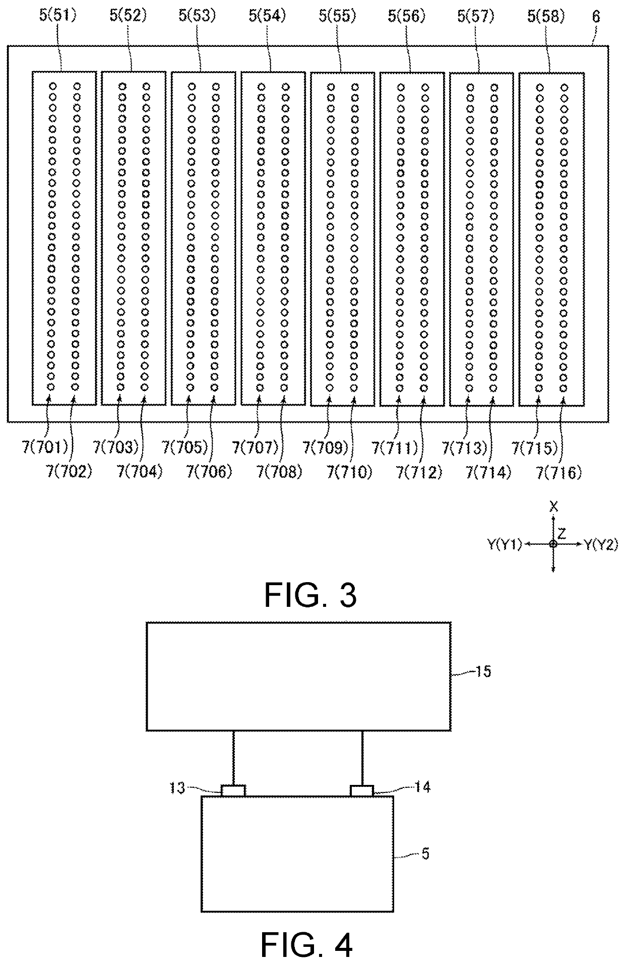
[0036]FIG. 1 is a block diagram for explaining an adjustment method of a shaping device 1 according to the embodiment of the present disclosure. FIG. 2 is a schematic view for explaining a configuration of a device body 2 shown in FIG. 1. FIG. 3 is a schematic view for explaining a configuration of an inkjet head 5 shown in FIG. 2. FIG. 4 is a schematic view for explaining a configuration of an inkjet head 5 shown in FIG. 2.

[0037]The shaping device 1 is an inkjet printer for manufacturing a stereoscopic shaped object (three-dimensional shaped object). The shaping device 1 includes a device body 2, which is a body of the shaping device 1 and a personal computer (PC) 3 incorporated in the shaping device 1. The device body 2 includes a table 4 on which a shaped object is shaped, an inkjet head 5 (hereinafter referred to as “he...


PUM

PropertyMeasurementUnit
weightaaaaaaaaaa
voltageaaaaaaaaaa
ink weight measurementaaaaaaaaaa

Abstract

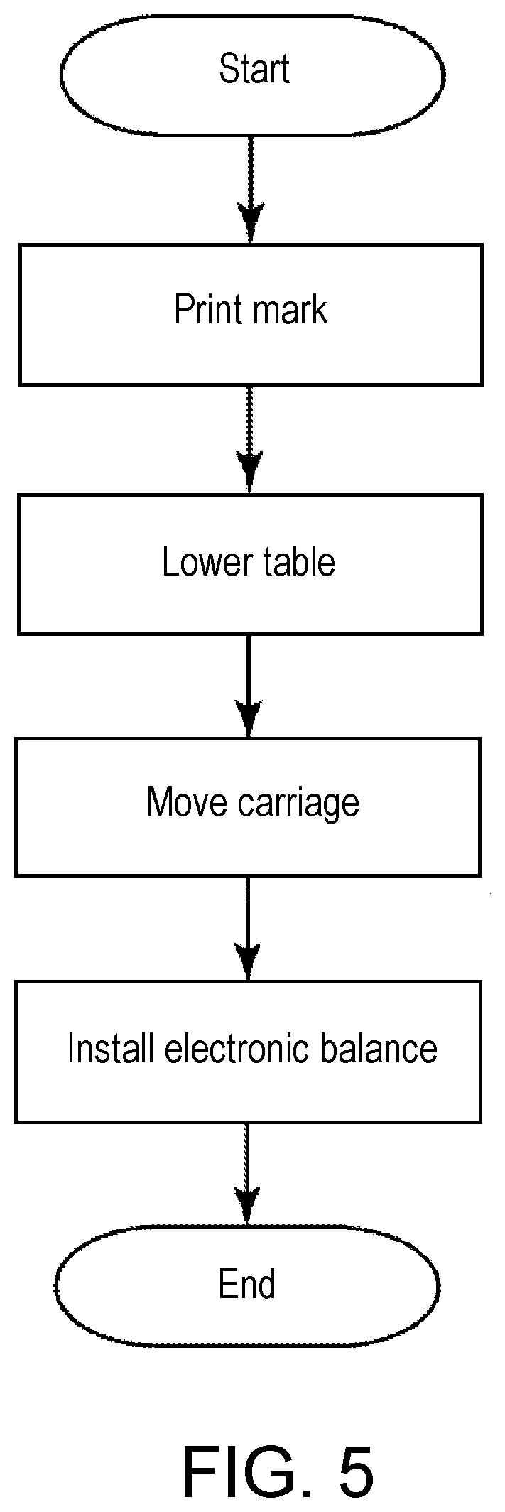
An adjustment method of a shaping device including a table on which a stereoscopic shaped object is shaped, and an inkjet head that ejects ink toward the table to form the shaped object, the method including an electronic balance installation process of placing an electronic balance for measuring weight of an ink ejected by the inkjet head on the table, and an ink ejection amount setting process of measuring the weight of the ink ejected by the inkjet head by the electronic balance placed on the table, and adjusting and setting the amount of ink ejected by the inkjet head based on the measurement result.

Description

CROSS REFERENCE TO RELATED APPLICATIONS[0001]This application claims the priority benefit of Japanese Patent Application No. 2018-120605, filed on Jun. 26, 2018, and Japanese Patent Application No. 2018-209962, filed on Nov. 7, 2018. The entirety of each of the above-mentioned patent applications is hereby incorporated by reference herein and made a part of this specification.TECHNICAL FIELD[0002]The present disclosure relates to an adjustment method of a shaping device that manufactures a stereoscopic shaped object.DESCRIPTION OF THE BACKGROUND ART[0003]Conventionally, a shaping device (three-dimensional shaped object manufacturing device) for manufacturing a stereoscopic shaped object is known (see, e.g., Japanese Unexamined Patent Publication No. 2018-89963, Patent Literature 1). The shaping device described in Japanese Unexamined Patent Publication No. 2018-89963 includes a table on which a shaped object is shaped and placed, a plurality of inkjet heads for ejecting ink toward t...

Claims


Application Information

Patent Timeline
Patent Type & Authority Applications(United States)
IPC IPC(8): B29C64/393B33Y10/00B33Y50/02B29C64/112
CPCB33Y50/02B29C64/112B33Y30/00B29C64/20B33Y10/00B29C64/393
Inventor IMAI, KENTA
Owner MIMAKI ENG
Learn More