Manufacturing method for pipe structure

Inactive Publication Date: 2021-04-01
NORITZ CORP
View PDF0 Cites 0 Cited by
  • Summary
  • Abstract
  • Description
  • Claims
  • Application Information

AI Technical Summary

Benefits of technology

The present invention provides a method for making a pipe structure that eliminates the need for complicated processes after bending the pipe, such as cutting the ends. This method allows for the creation of pipe structures with aligned ends, such as meandering pipes, with greater efficiency and productivity.

Problems solved by technology

As a result, the productivity of the meandering pipe body A is poor, and the manufacturing cost thereof is high.
As a result, the problem described above remains unsolved.

Method used


Image

  • Manufacturing method for pipe structure
  • Manufacturing method for pipe structure
  • Manufacturing method for pipe structure

Examples


Embodiment Construction

[0037]A preferred embodiment of the present invention will be described specifically below with reference to the figures.

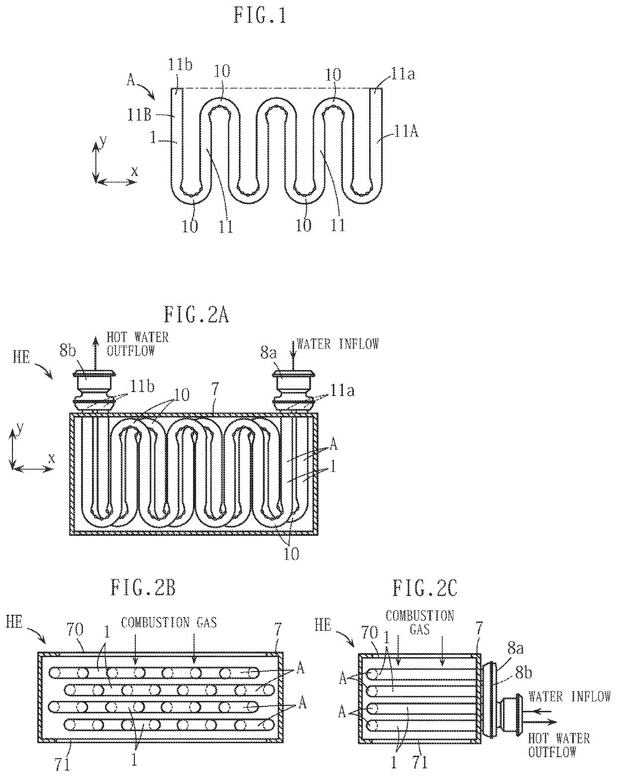
[0038]The manufacturing subject of the manufacturing method for a pipe structure according to this embodiment, similarly to the prior art described above, is the meandering pipe body A shown in FIG. 1. Accordingly, identical or similar elements to the prior art have been allocated identical reference symbols to the prior art.

[0039]First, the meandering pipe body A will be described.

[0040]As described above, the meandering pipe body A is constructed by forming the stainless-steel pipe 1, for example, in a meandering shape, and includes the plurality of bend portions 10, each of which has a bend angle of 180 degrees, and a plurality of straight portions 11 connected via the plurality of bend portions 10. The regions 11A, 11B near the respective end portions of the pipe 1 are separated from each other in the x direction, which is a horizontal width direction in FIG. ...


PUM

PropertyMeasurementUnit
Dimensionaaaaaaaaaa

Abstract

A manufacturing method for a pipe structure includes a pipe bending step for implementing for a plurality of times a bending process of bending a part of a straight pipe by wrapping the part around a peripheral surface of a rolling block to form a plurality of bend portions in intermediate locations along a longitudinal direction of the pipe. When a final bending process is implemented during the pipe bending step, a position of a rear end portion of the pipe is determined, and relative positions of the pipe and the rolling block in a predetermined y direction are controlled on the basis of the position of the rear end portion so that after the bending process, a y-direction position of the rear end portion is aligned with a y-direction position of the front end portion. According to this configuration, complicated operations such as cutting the respective end portions of the pipe after bending the pipe can be eliminated, and a pipe structure such as a meandering pipe body in which the positions of the respective end portions are aligned can be manufactured appropriately and with favorable productivity.

Description

BACKGROUND OF THE INVENTIONField of the Invention[0001]The present invention relates to a method for manufacturing a pipe structure having a meandering shape, a spiral shape, or the like, for example, which is used as a constituent element of a heat exchanger or the like.Description of the Related Art[0002]A meandering pipe body A such as that shown in FIG. 1, for example, is available as a pipe structure used as a heat transfer pipe of a heat exchanger. The meandering pipe body A is constructed by forming a stainless-steel pipe 1 in a meandering shape, and includes a plurality of bend portions 10. Regions 11A, 11B near respective end portions of the pipe 1 are separated from each other in an x direction and extend in a y direction that intersects the x direction.[0003]A method shown in FIG. 12, for example, is available as a method for manufacturing the meandering pipe body A. This manufacturing method includes a pipe manufacturing and press-cutting step S1, a pipe bending step S2,...

Claims


Application Information

Patent Timeline
IPC IPC(8): B21D7/025B21D7/028B21D53/02B21D53/06
CPCB21D7/025B21D53/06B21D53/027B21D7/028B21D7/14F28D7/082F28D7/02B21D11/06
Inventor SE, NAOKITERASAWA, TAIHEIOKUDA, SHOJIFUJISAWA, HIDEYUKIKOYAMA, MOTOSHI
Owner NORITZ CORP
Why Eureka
Try Eureka