Electromagnetic valve and use thereof

a technology of electromagnetic valve and valve body, which is applied in the direction of lift valve, valve details, engine components, etc., can solve the problems of not being able to achieve or only difficult to achieve with the technology according to the class, and the known valve principle is not optimal for all conceivable embodiments, so as to improve the service life, wear and sealing properties, and improve the sealing tightness. , the effect of improving the sealing properties

Active Publication Date: 2019-01-24
ETO MAGNETIC GMBH
View PDF17 Cites 0 Cited by
  • Summary
  • Abstract
  • Description
  • Claims
  • Application Information

AI Technical Summary

Benefits of technology

[0019]As a result, by means of the present invention, the technology known from the most recent background art is improved in a surprisingly simple and elegant way, and, improved both with respect to service life, wear and sealing properties, as well as regarding being suitable for a (for example, pretensioned by spring force) closed valve without any flow (sealing without any flow), which is favourably sufficient for the increased sealing tightness requirements of a pneumatic fluid.
[0020]Thereby, in accordance with the use

Problems solved by technology

While such a technology according to the preamble has been tried and tested for the intended purpose within the scope of a pressure regulator for a hydraulic transmission control system and is produced in large quantities, the known valve principle is, at the same time, not optimal for all conceivable embodiments.
However, in particular, implementation of a valve with a closed function without any flow occurring, where, namely, the sealing body is pretensioned against the valve seat usually by means of pressure spring action or similar force retention means if there is no flow into the coil means and thereby, no electromagnetic armature actuation occurs, is practically not capable of being achieved or only difficult to achieve with the technology according to the class at hand.
On the one hand namely, this explicitly provides an armature pretensioning by means of the spring against a locking device; on the other hand, the known embodiment of the sealing body as a full polymer would also sign

Method used


Image

  • Electromagnetic valve and use thereof
  • Electromagnetic valve and use thereof

Examples


Embodiment Construction

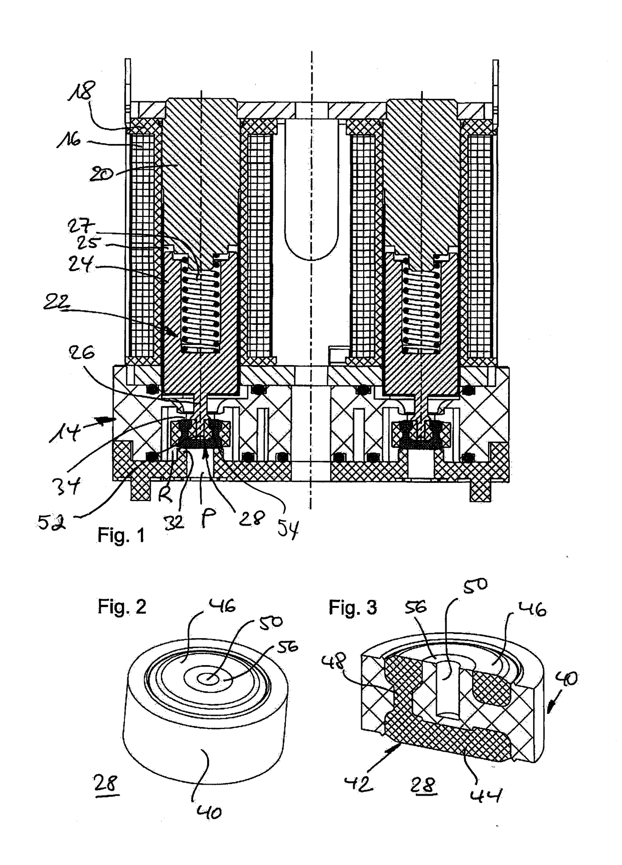
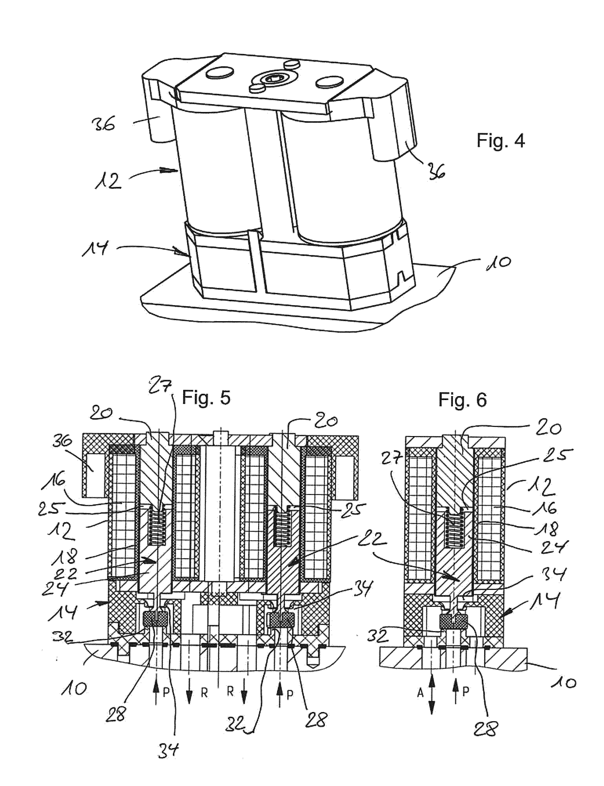
[0027]In a prospective view, FIG. 4 shows a use context of the electromagnetic valve according to the invention in accordance with a first exemplary embodiment as a pair of electromagnetic valves, which are arranged adjacent to one another and mounted to an underlying unit, which is not further specified. FIGS. 5 and 6 show longitudinal cross sections of such an apparatus, wherein the view of FIG. 6 in relation to the cross-sectional view of FIG. 5 is rotated by 90° around a (vertical) axis; FIG. 6 only shows an arrangement of the pair accordingly.

[0028]Each of the electromagnetic valves has, lying on top in the figure plane, a coil area 12, to which a lower connection and valve seating area 14 connects. In turn, in the case of the embodiment of the electromagnetic valves as a 3 / 2 valve respectively, meaning with three connections and two switch positions, a valve inlet P and outlets A and R are provided, wherein, as is evident from the comparison in FIGS. 5 and 6, in the case of th...


PUM


Abstract

The invention relates to an electromagnetic valve with armature means (22) which are designed to be movable along an axial direction in a valve housing (14) as a reaction to current flowing through stationary coil means (16) and which at one axial end have sealing means (28) designed to interact with a valve seat (32) assigned to a first valve inlet (P), wherein at least one second valve inlet and/or outlet (A, R) in the valve housing can be opened to the first valve inlet (P) by action of the armature means, and wherein the sealing means are provided as sealing bodies (28) on a portion (26) of the armature means of narrowed diameter, such that the sealing body having a larger diameter compared to the narrowed portion can be moved by the movement of the armature means between sealing positions formed at both axial ends of the sealing body, wherein the sealing body (28) designed as a component separate from the narrowed portion and/or designed to be releasable therefrom has a sealing portion (42), made of a polymer and/or rubber material, and also a support portion (40) which is made of a material different than and in particular harder than the material of the sealing portion, and which is designed for force-fit connection to the armature means.

Description

BACKGROUND OF THE INVENTION[0001]The present invention relates to an electromagnetic valve according to the preamble of the main claim. Furthermore, the present invention relates to the use of such an electromagnetic valve.[0002]Electromagnetic valves according to this class are generally known from the most recent background art; in the case of these, usually, the valve function is caused by means of an armature unit, designed to be moveable and provided in a valve housing relative to a stationary coil means, which, being typically provided with a sealing means, can open or close an assigned valve seat of an inlet or an outlet of the magnetic valve in controlled manner according to the current-flow status of the coil means and an armature position caused thereby.[0003]A preferred field of application for the use of such a technology presumed to be generic and generally known is automotive technology; here, for example, known electromagnetic valves according to the class are suitabl...

Claims


Application Information

Patent Timeline
IPC IPC(8): F16K31/06F16K1/46F16K27/00
CPCF16K31/0627F16K1/465F16K27/003F16K31/0606F16K31/0675F16K1/46
Inventor RAFF, VIKTORTHODE, OLIVER
Owner ETO MAGNETIC GMBH
Why Eureka
Try Eureka