System for improved weapon system barrel

a technology of weapon system and barrel, which is applied in the field of weapon barrel, can solve the problems of reducing the accuracy of the projectile expelled from the barrel and the ability of the shooter

Active Publication Date: 2019-01-24
TELUDYNE TECH INDS
View PDF4 Cites 1 Cited by
  • Summary
  • Abstract
  • Description
  • Claims
  • Application Information

AI Technical Summary

Benefits of technology

[0012]The above objectives are accomplished according to the present invention by providing a method of modifying a firearm barrel comprising the steps of milling an existing barrel to create a sloped area with a larger diameter at a chamber end and a small action moving toward the muzzle end; placing an barrel nut on the barrel; placing a chamber bushing having a step with the step disposed at the chamber end; placing a brass pressing guide on the barrel and placing the barrel assembly with brass press guide and rear jacket tube in a press to press fit these components together; placing a gas block on the barrel adjacent to the rear jacket tube pressing the components tougher using the press; placing a front jacket tube on the barrel adjacent to the gas block and pressing the components tougher using the press; covering the threads of the barrel and placing a pour guide on the barrel; filling a void defined between the front jacket tube, rear jacket tube, and barrel with a filler; placing a centering device on the barrel so that it is operatively associated with the front jacket tube to center the barrel in the front jacket tube while the filler is curing; placing a muzzle brake cap on the barrel and pressing the muzzle cap into the front jacket tube using the press; and, attacking a muzzle brake.

Problems solved by technology

Barrel whip reduces the accuracy of the projectile expelled from the barrel and, therefore, the ability of a shooter to hit a target.

Method used


Image

  • System for improved weapon system barrel
  • System for improved weapon system barrel
  • System for improved weapon system barrel

Examples


Embodiment Construction

[0016]With reference to the drawings, the invention will now be described in more detail. Unless defined otherwise, all technical and scientific terms used herein have the same meaning as commonly understood to one of ordinary skill in the art to which the presently disclosed subject matter belongs. Although any methods, devices, and materials similar or equivalent to those described herein can be used in the practice or testing of the presently disclosed subject matter, representative methods, devices, and materials are herein described.

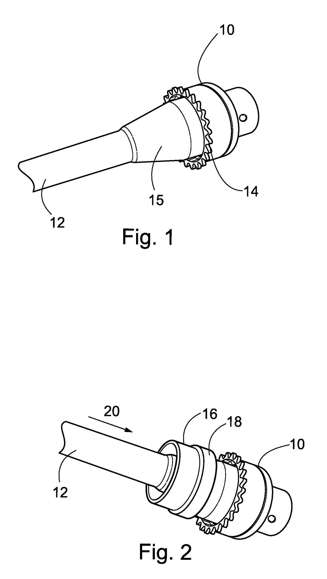
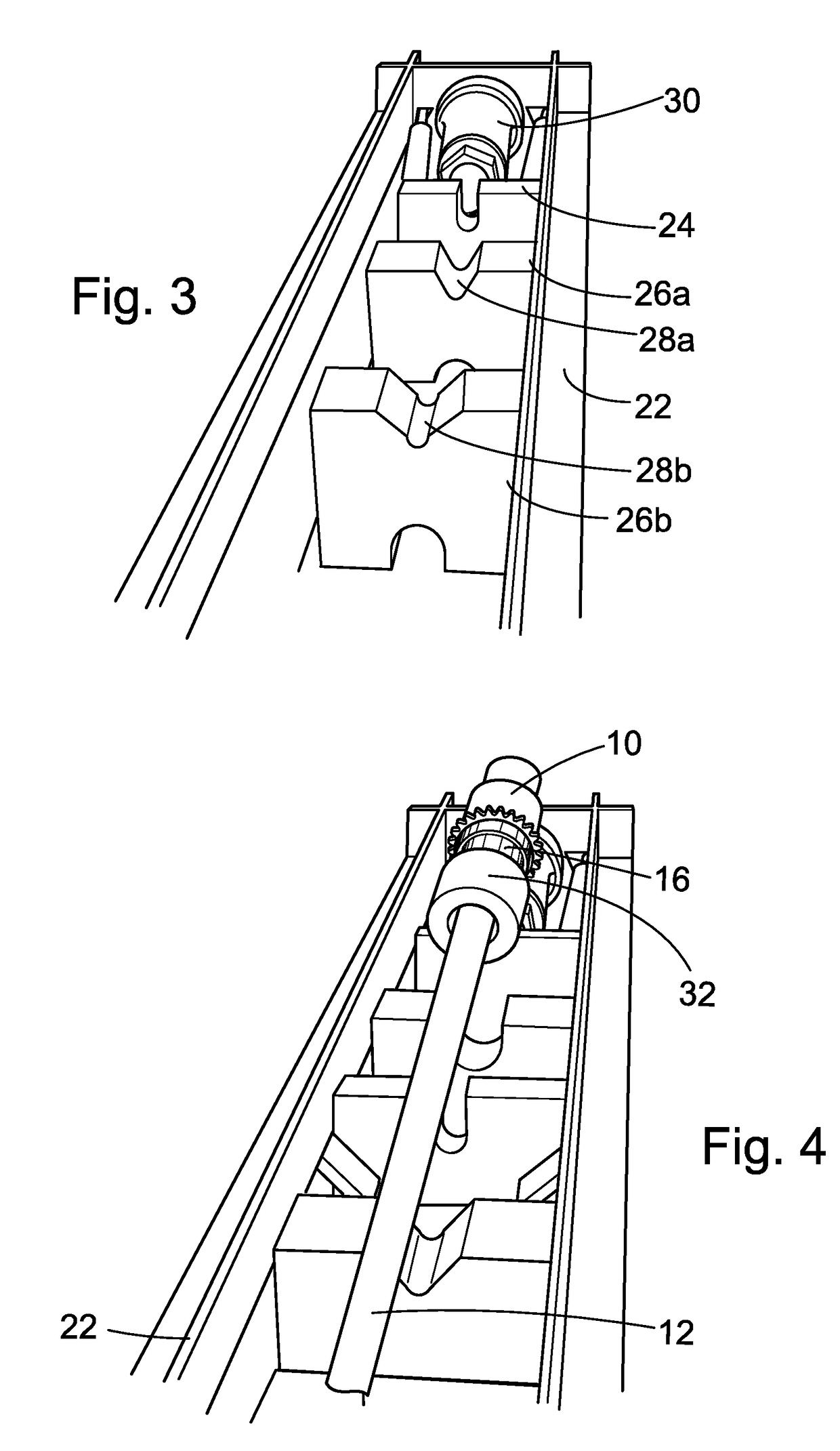
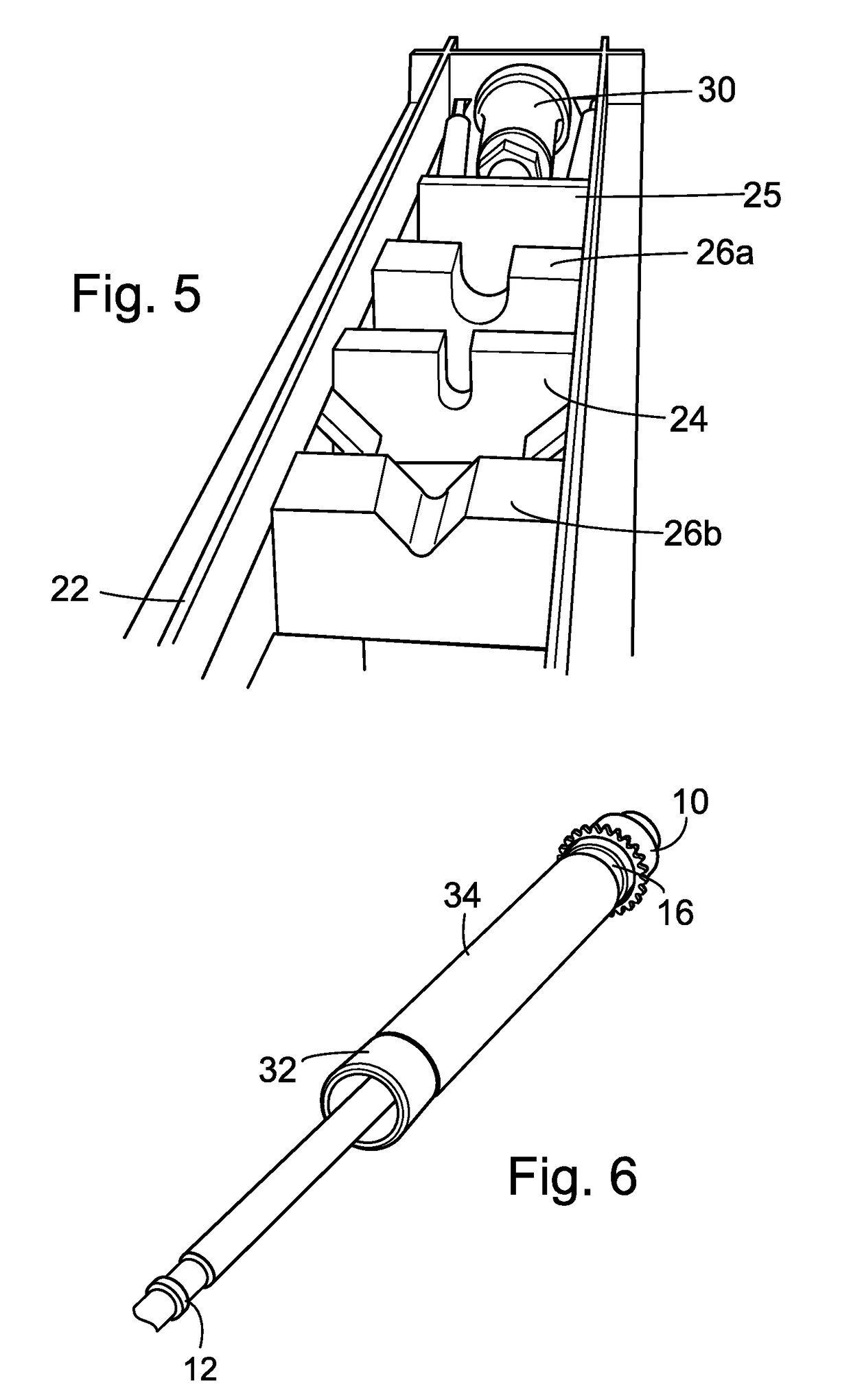
[0017]Referring to FIG. 1, a barrel nut 10 can be placed over the barrel 12 with threads towards the breach and knurled end 14 toward the muzzle. Referring to FIG. 2, a chamber bushing 16 can be placed over the barrel 12 with step 18 towards the breach direction, designated generally as 20, and in a position for press fitting. It is preferred the barrel nut 10 is in position prior to hand pressing the chamber bushing 16 in place as a quality control...


PUM


Abstract

A method of modifying a firearm barrel comprising the steps of milling an existing barrel to create a sloped area with a larger diameter at a chamber end and a small action moving toward the muzzle end; placing an barrel nut on the barrel; placing a chamber bushing having a step with the step disposed at the chamber end; placing a brass pressing guide on the barrel and placing the barrel assemble with brass press guide and rear jacket tube in a press to press fit these components together; placing a gas block on the barrel adjacent to the rear jacket tube pressing the components tougher using the press; placing a front jacket tube on the barrel adjacent to the gas block and pressing the components tougher using the press; covering the threads of the barrel and placing a pour guide on the barrel; filling a void defined between the front jacket tube, rear jacket tube and barrel with a filler; placing a centering device on the barrel so that it is operatively associated with the front jacket tube to center the barrel in the front jacket tube while the filler is curing; placing a muzzle brake cap on the barrel and pressing the muzzle cap into the front jacket tube using the press; and, attacking a muzzle brake.

Description

BACKGROUND OF THE INVENTION[0001]1) Field of the Invention[0002]The present invention relates to weapon barrels, and more particularly, to the construction of a rifle, shotgun, or cannon barrel and methods of modification providing a layered barrel design for reducing heat and harmonics and for improving accuracy.[0003]2) Description of Related Art[0004]It has been long understood that a rifle's barrel changes shape and moves in multiple directions every time the rifle is fired. This effect is also found in shotgun and cannon barrels. In some instances, this movement of the barrel has been coined “barrel whip” and is when a weighted object (bullet) travels down the tubular barrel under intense gas pressure generally defined as when the barrel away from its “static” state. Barrel whip can occur when the bullet accelerates into a rapid spin, when the stock drops significantly so the muzzle rises when the rifle is fired, or when a pressure wave travels the length of the barrel. In the ...

Claims


Application Information

Patent Timeline
Patent Type & Authority Applications(United States)
IPC IPC(8): F41A21/26F41A21/16F41A21/48
CPCF41A21/26F41A21/16F41A21/48F41A5/26F41A21/02F41A21/44F41A27/30F41C27/22
Inventor ALDOPHSEN, ALAN
Owner TELUDYNE TECH INDS
Why Eureka
Try Eureka