
Eureka
For R&D, Eureka makes reading and utilizing patents & technical documents easy.
Eureka AIR
Designed for self-driven R&D workflows. Generate viable solutions, solve complex R&D challenges, empower your innovation with AI.

Eureka Materials
Designed for material experts only. Revolutionize your material R&D, from search, analyze, to developing new materials.

TechResearch
Generate reliable direction feasibility study reports for your R&D in just a few steps.

TechSeek
Discover and master advanced knowledge NOW. Basics, ideas, possibilities, all at once.

TechMind
As an expert in R&D Theories, TechMind can generates customized viable solutions instantly.

TechRisk
Analyze your overall solution with one click, know your potential R&D risks in advance.

TechMonitor
Get weekly tech updates, stay abreast of the latest tech innovations and key insights.
Image reading apparatus and reading module
- Summary
- Abstract
- Description
- Claims
- Application Information
AI Technical Summary
Benefits of technology
Problems solved by technology
Method used
Image

Examples
first embodiment
[0037]Hereinafter, a first embodiment embodying an image reading apparatus will be described with a reference to the drawings. The image reading apparatus according to the first embodiment is, for example, a multi-function peripheral provided with a scanner device.
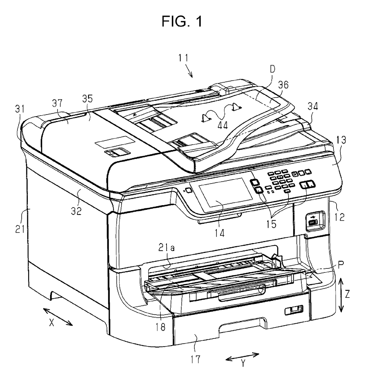
[0038]As illustrated in FIG. 1, a multi-function peripheral 11 includes a printing device 21 for performing printing on a medium P such as a sheet, and a scanner device 31 that is disposed on the upper side of the printing device 21 in a vertical direction Z and can read a document D. The multi-function peripheral 11 has functions of scanning, copying and printing.
[0039]An operation panel 13 provided in a device main body 12 of the multi-function peripheral 11 includes a display 14 for displaying a menu screen and the like and an operation unit 15 including operation switches and the like. For example, by operating the operation unit 15, requests for scanning, copying, and printing are given to the multi-function periphera...
second embodiment
[0092]Next, a second embodiment will be described with reference to FIG. 9. In this second embodiment, by inclining the reading module 50 with respect to the housing 55, the optical axis L2 of the reading element 53 (that is, the image forming element 56) is inclined with respect to the normal line N1 of the glass plates 33A and 39A (that is, the reading surface Dp) by the second angle θL toward the side (counterclockwise direction in FIG. 9) where the incident angle θ1 of the light from the linear light source 52 to the glass plates 33A and 39A is increased. As described above, since the housing 55 is inclined as a whole, the image forming element 56 is disposed such that the optical axis L2 thereof is along the normal line N2 of the facing surface 55B facing the glass plates 33A and 39A of the housing 55. Here, the optical path length from the document D to the incident port of the image forming element 56 (that is, the lens array 562) constituting the reading element 53 is set to...
third embodiment
[0095]Next, a third embodiment will be described with reference to FIG. 10. In the third embodiment, the reading element 53 is configured so that the angle can be adjusted.
[0096]As illustrated in FIG. 10, the reading module 50 includes an angle adjusting unit 110 for adjusting the inclination angle defined by the angle formed between the optical axis L2 of the reading element 53 and the normal line N1 of the document surface Dp. The angle adjusting unit 110 includes an angle adjustment mechanism 111 capable of adjusting the incline angle of the reading element 53, and an actuator 112 such as an electric motor for giving power for changing the inclination angle of the reading element 53 to the angle adjustment mechanism 111. The angle adjustment mechanism 111 supports the reading element 53 from both sides in the longitudinal direction of the reading element 53 in a state in which the inclination angle thereof can be changed. The angle adjustment mechanism 111 is configured so that t...
PUM
 Abstract
Description
Claims
Application Information
 - R&D Engineer
- R&D Manager
- IP Professional
- Industry Leading Data Capabilities
- Powerful AI technology
- Patent DNA Extraction
Browse by: Latest US Patents, China's latest patents, Technical Efficacy Thesaurus, Application Domain, Technology Topic, Popular Technical Reports.
© 2024 PatSnap. All rights reserved.Legal|Privacy policy|Modern Slavery Act Transparency Statement|Sitemap|About US| Contact US: help@patsnap.com