
Systems and Methods for Light Field Generation

a technology of light field and system, applied in the field of system and method for light field generation, can solve the problems of unmitigated saw propagation, image motion, unsatisfactory scattering, etc., and achieve the effect of limiting the peak power required

Inactive Publication Date: 2019-01-24
CHARLES STARK DRAPER LABORATORY
View PDF0 Cites 5 Cited by
  • Summary
  • Abstract
  • Description
  • Claims
  • Application Information

AI Technical Summary

Benefits of technology

This invention is about improving the performance of light field generators, such as holographic display systems, by using specific techniques to reduce peak power requirements and cancellation of wave propagation among light signals. This can be achieved by using AOMs, such as SAW modulators, which can help to enhance the overall quality of the display.

Problems solved by technology

However, the same SAW that would cause light to scatter from the left side of the waveguide will then travel to the right side of the waveguide, where it would cause undesirable scattering.
One undesirable outcome of unmitigated SAW propagation is image motion, which is usually perceived as image blur by an observer.
While this works, it also typically requires thick form-factors and moving parts.

Method used


Image

  • Systems and Methods for Light Field Generation
  • Systems and Methods for Light Field Generation
  • Systems and Methods for Light Field Generation

Examples


Embodiment Construction

[0043]The invention now will be described more fully hereinafter with reference to the accompanying drawings, in which illustrative embodiments of the invention are shown. This invention may, however, be embodied in many different forms and should not be construed as limited to the embodiments set forth herein; rather, these embodiments are provided so that this disclosure will be thorough and complete, and will fully convey the scope of the invention to those skilled in the art.

[0044]As used herein, the term “and / or” includes any and all combinations of one or more of the associated listed items. Further, the singular forms and the articles “a”, “an” and “the” are intended to include the plural forms as well, unless expressly stated otherwise. It will be further understood that the terms: includes, comprises, including and / or comprising, when used in this specification, specify the presence of stated features, integers, steps, operations, elements, and / or components, but do not pre...


PUM

PropertyMeasurementUnit
acoustic velocityaaaaaaaaaa
thicknessaaaaaaaaaa
thicknessaaaaaaaaaa

Abstract

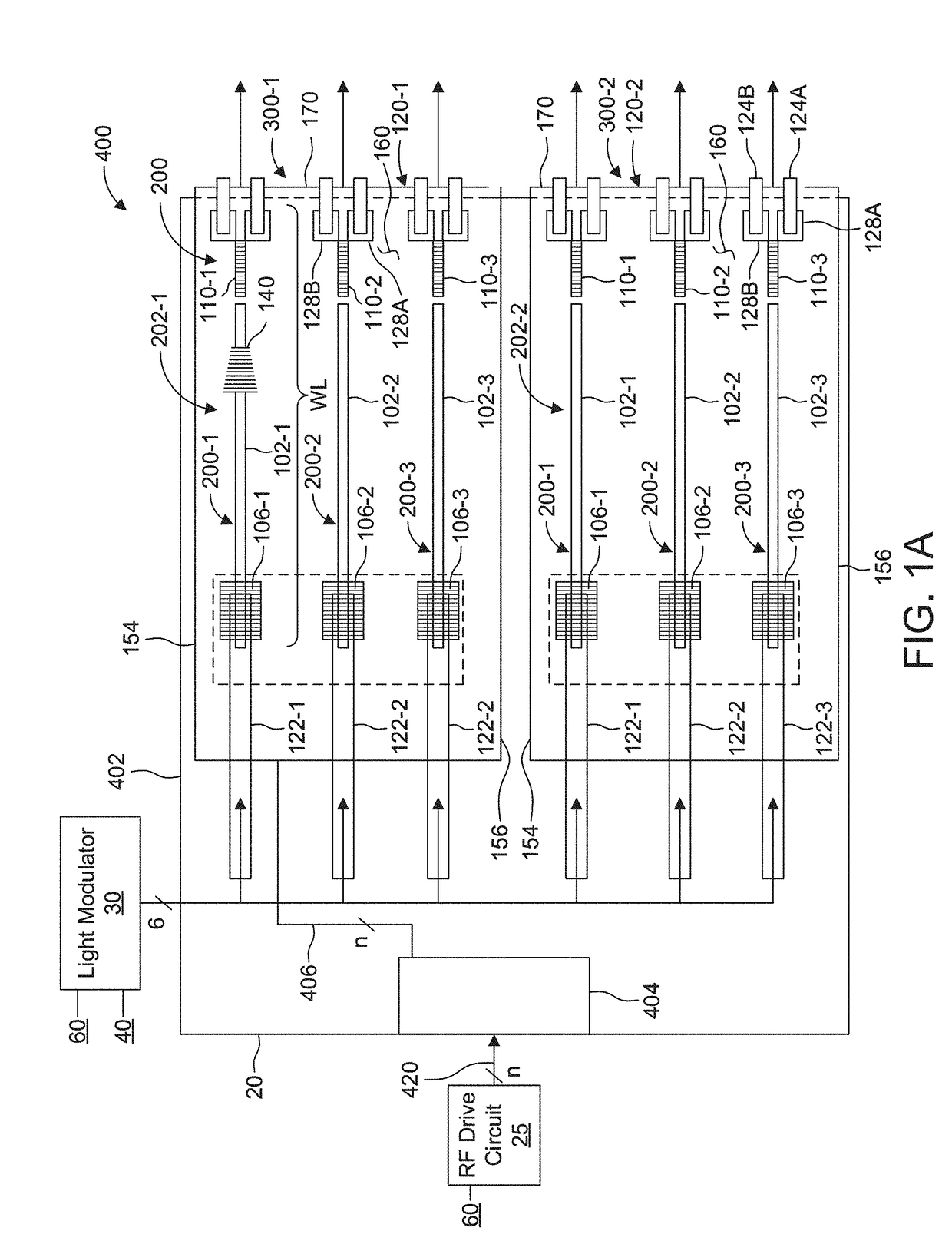
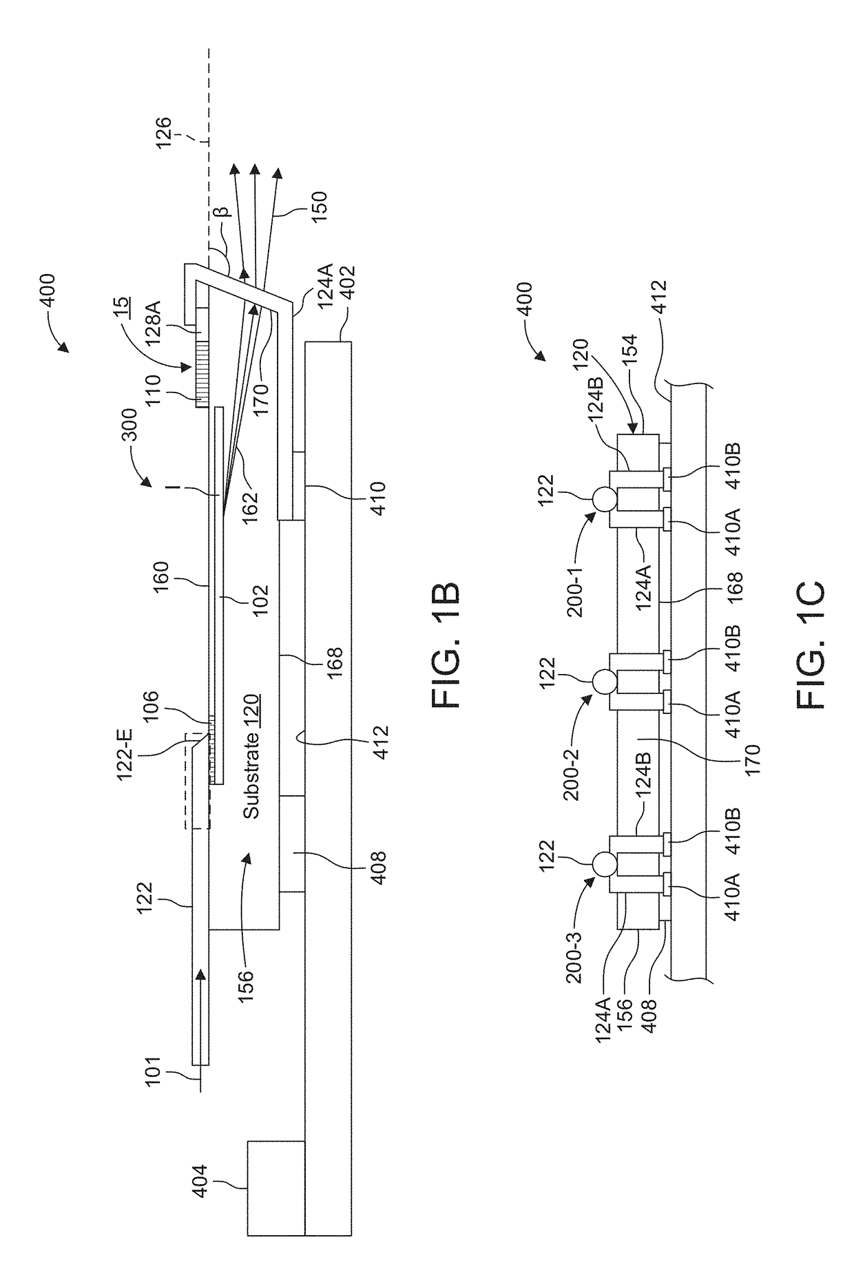
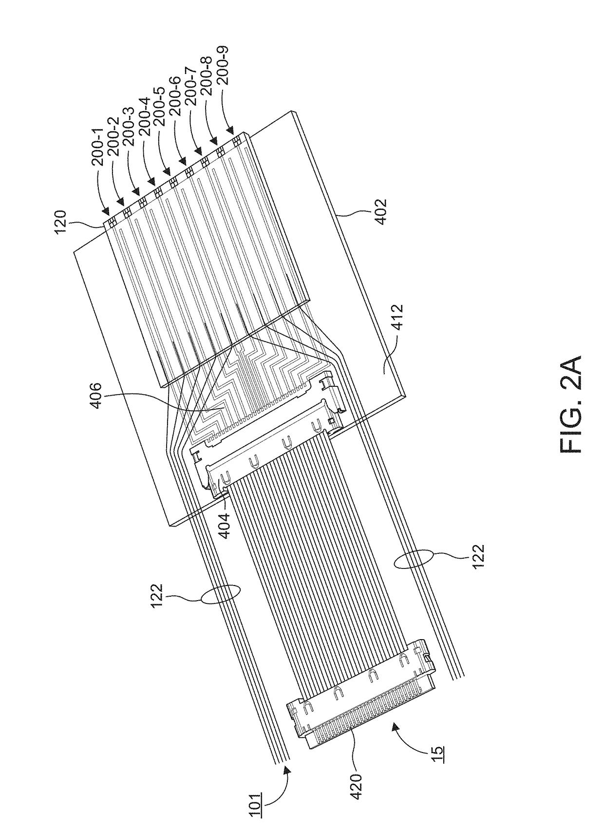
A system and method for light field generation is disclosed. A proposed holographic display system encodes views of a scene into surface acoustic waves (SAW signals) that propagate along waveguides of SAW modulators and / or optical signals propagating in the waveguides. Each view provides a different perspective of the scene when the views are projected as light fields out of the SAW modulators and are viewed at different locations by an observer. In some examples, the system encodes the brightness information for each view into the light signals.

Description

RELATED APPLICATIONS[0001]This application claims the benefit under 35 USC 119(e) of U.S. Provisional Application No. 62 / 534,866, filed on Jul. 20, 2017, which is incorporated herein by reference in its entirety.BACKGROUND OF THE INVENTION[0002]Acousto-optic modulators (AOMs) show promise as components of light display systems for generating light fields as are required for holographic displays and other applications. One class of AOMs are termed surface acoustic wave (SAW) optical modulators. These modulators can provide controllable sub-holograms from which a light field can be constructed.[0003]One type of SAW modulator is the guided-to-leaky-mode device fabricated using lithium niobate as described, for example, in Hinkov et al., Collinear Acoustooptical TM-TE Mode Conversion in Proton Exchanged Ti:LiNbO3 Waveguide Structures, J. Lightwave Tech., vol. 6(6), pp. 900-08 (1988), Smalley et al., Anisotropic leaky-mode modulator for holographic video displays, Nature, vol. 498, pp. 3...

Claims


Application Information

Patent Timeline
Patent Type & Authority Applications(United States)
IPC IPC(8): G02F1/33G02F1/313G03H3/00
CPCG02F1/332G02F1/3136G03H3/00G03H2225/60G03H1/2294G03H2001/0224G03H2225/23
Inventor BYRNES, STEVEN J.FAVALORA, GREGG E.FRANK, IAN WARDKOPA, ANTHONYMOEBIUS, MICHAEL G.REGISTER, JOSEPH J.
Owner CHARLES STARK DRAPER LABORATORY
Learn More